Tag Archive for: iTestSystem

Another Successful Condition Monitoring System Installation


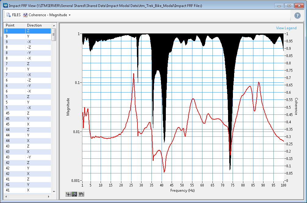
Last week our team successfully and safely installed another Boiler Monitoring System (BMS).  This system, a Sootblower Fouling Detection (SFD) system, monitors structural and vibration sensors that quantify the boiler’s response to sootblower operations. The SFD system analyzes the boiler response data and outputs Key Performance Indicators (KPIs) such as fouling level, sootblower efficiency, and sootblower health to automated boiler cleaning systems.

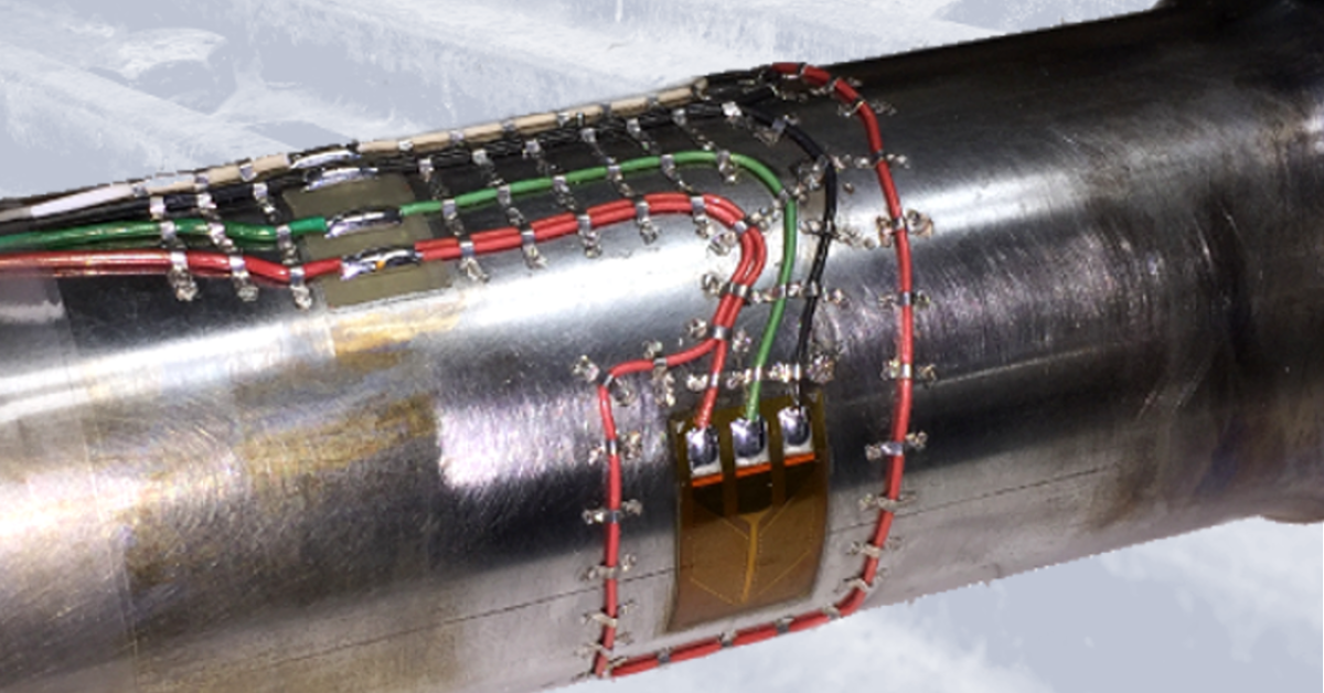
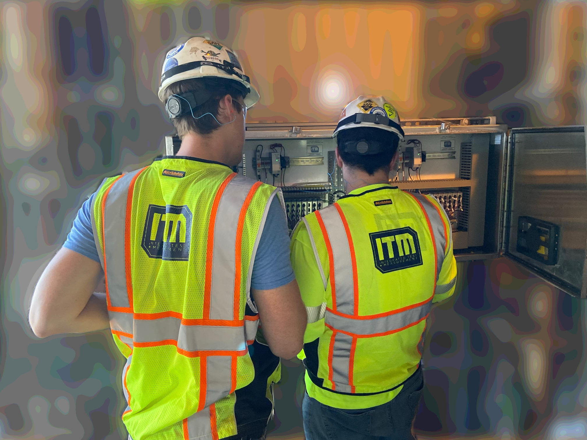
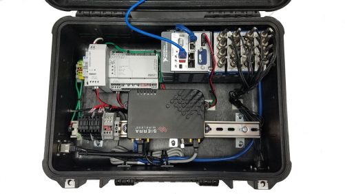
This boiler uses over 50 sootblowers located at different elevations to clean soot build-up from boiler steam tubes.  Since the vibration measurement locations are relatively far apart, the SFD system requires a distributed monitoring system consisting of several junction  boxes that monitor and process data for groups of sensors.  One team of engineers mounted the vibration sensors to the sootblowers and confirmed communication back to a local junction box containing the National Instruments condition monitoring hardware.  The other team installed the junction box panels and terminated the sensor cables.

After all the sensor installations and terminations were completed, each sensor’s location and calibration were verified.  While the sensor verification was being completed, one engineer worked with the mill IT department and the controls engineer to establish remote connection to the system and confirm communication with the mill’s automated cleaning system.

After commissioning the system and returning to our home base, our engineers are now monitoring the system through a VPN connection and assisting boiler operators with optimizing their cleaning process.

For more information about our ryan.welker@iTestSystem.com or phone @ 1.844.837.8797 x702

iTestSystem Tip: Sensor Auto-zero Utility Update


Our iTestSystem customers who routinely acquire data with high channel counts and data from full-bridge transducers recently requested that we update the sensor auto-zero utility to improve test setup efficiency.   In the latest version of iTestSystem, we updated the sensor auto-zero utility to include all channels that use the From Custom Scale option.  This update enables users to quickly adjust selected channel offsets with only a few mouse clicks.

One of our test engineers recently used this feature to test and calibrate a new load cell design for measuring loads in a manufacturing process.  He was able to quickly calibrate and zero the strain gauges along with a calibrated load cell and a pressure transducer prior to testing and before each directional test. The offset values are included in the calibration data files for traceability.

Contact Information: For more information about this update or iTestSystem contact:

Chase Petzinger – Integrated Test & Measurement (ITM), LLC. Email: chase.petzinger@itestsystem.com or Phone: 1.844.TestSys

Machine Failures Caused by Intermittent Damaging Events

Over the years we have been tasked with identifying the root cause of machine structural failures. In many cases, we can determine the failure mode through strain and vibration testing, order analysis, modal analysis, and operating deflection shape analysis.  What tests can you run when the damaging conditions are intermittent and not easily identified?

In these cases, we like to install a cellular networked temporary data acquisition (DAQ) system that can autonomously log vibration and strain data along with machine status data. We have deployed two types of DAQ systems to collect data remotely.  An interactive system that includes an industrial PC running our iTestSystem software and National Instruments (NI) Compact DAQ hardware and a headless system that utilizes NI Compact RIO hardware.  Our test engineers prefer using the interactive solution for troubleshooting because they can view real-time signal waveforms and collected data files, and then adjust the test parameters accordingly without having to reprogram the hardware.

Rugged Measurement System

Figure 1: Headless networked data acquisition system

When potentially damaging events are identified in the vibration and strain data collected by these systems, it is important to know the machine’s operating status. Collecting the machine status information is just as important as collecting the structural data.  Many machines transmit these operating variables and operating stages over their network/bus.  Recently we have recorded process data from Allen Bradley Control Logix PLCs via Ethernet/IP, mining machine data from a Siemens controller via proprietary TCP/IP protocol, boiler condition data from a DCS via Modbus TCP,  machine pressures from PI historian via the UFL connector (TCP), and vehicle speeds and pressure via CAN.  Fortunately, we were able to use and adapt LabVIEW communication protocol tools to build applications and addons that allow this network tag data to be collected along with structural data.

LabVIEW Modbus to Shared Variable Code

Figure 2: Modbus to Shared Variable Tool

After the data collection phase, our engineers perform statistical analysis on the sensor and status channels in all data files and aggregate the results into a database for searchability. To identify the root cause probabilities, you can process the channel statistics data using your favorite correlation algorithm or application.  The image below shows an example data set containing related sensor data that was processed using a LabVIEW correlation test tool.

LabVIEW Correlation VI

Figure 3: Correlation Test Example vi

Contact Information: For more information about our remote data acquisition service, our LabVIEW development service, or iTestSystem contact:

Mark Yeager – Integrated Test & Measurement (ITM), LLC.  Email: mark.yeager@itestsystem.com or Phone: 1.844.TestSys

Recent News:  Ohio University Asphalt Cracking Prediction System Project

ITM adds NI-9253 Compatibility to iTestSystem

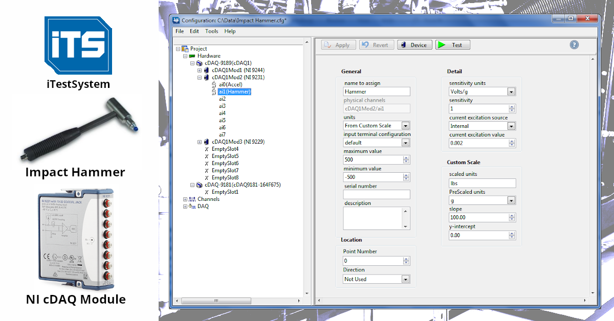
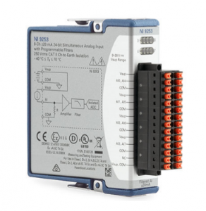
This week we added another module to the iTestSystem compatibility list.  One of our iTestSystem users recently needed to collect data from thirty-two (32), 4 to 20 mA current sensors along with their vibration measurements.  National Instruments (NI) recently introduced a new C-Series current module, the NI-9253, that was a perfect fit for this application.

The NI-9253 module has eight (8) simultaneous sampled (50kHz max), +-20 mA, 24-bit input channels.  It has several diagnostic features to ensure your system is operating nominally at all times with open channel detection, power supply detection, and configurable thresholds. The NI-9253 has eight LEDs that indicate the status of each channel and the power supply so a user can easily determine the system’s status in the field.  The NI-9253 also features a number of programmable hardware filters (Butterworth and comb) to reduce signal noise.

in iTestSystem monitoring applications or with custom cRIO RT and FPGA control applications contact Mark Yeager or Chase Petzinger.

Strain Gauge Installations for Field Testing

shaft torque sensor

Image1: Shaft torque strain gauge installation example for field testing

Our engineers and technicians have epoxied, soldered and spot welded strain gauges for applications ranging from high temperature exhaust systems to miniature load cell measurements. Every application requires a unique understanding of the strain measurement requirements including installation environment.

If the strain gauge installation is to survive in the field you must plan for the conditions it will undergo. Three important variables that you should account for are temperature range, liquid exposure, and potential impact forces. These variables determine the type of strain gauge, epoxy, solder, wiring, coating, and impact/wear protection to use in the application. The table below shows which variables affect your installation choices.

  Gauge Epoxy Solder Wiring Coating Covering
Temperature  
Liquid Exposure      
Impact Forces      

Table1: Strain gauge installation variables

For more information about ITM’s strain gauging services contact Ryan Welker at email: ryan.welker@itestsystem.com or phone: 1.844.837.8797 x702

Roving Accelerometer Impact Tests with iTestSystem

3D Animator: Bike Frame Twist Vibration Mode at 26.2 Hz

In order to prevent or troubleshoot structural vibration problems, it is important to characterize a structure’s dynamic behavior using both experimental and Finite Element Analysis (FEA) technologies.  One method used to identify a structure’s vibration modes is to perform a roving accelerometer or roving hammer impact test.  In an impact test, engineers measure the response of a structure from an impulse delivered by a calibrated hammer using tri-axial accelerometers.

FRF View: Bike Frame Point 9 Coherence & Magnitude

Managing impact tests on large structures can be tedious and cost prohibitive, since they require collecting accelerometer responses at hundreds of locations to resolve the vibration motion.  Not only do test engineers need to keep track of the locations, they also need to keep track of the orientation that an accelerometer is positioned.

Our test engineers have found that the most efficient and cost effective solution for collecting impact data is to use a National Instruments (NI) cDAQ chassis with either NI-9234, NI-9232, NI-9231 or NI-9230 IEPE modules along with a calibrated impulse hammer and between 3 – 9 tri-axial accelerometers. To collect, manage, and visualize the modal data, our LabVIEW software engineers developed the Impact Test DAQ, FRF Viewer, and 3D Animator applications for our iTestSystem software platform. These applications incorporate tools that our test engineers need to manage and validate the quality of their modal data while in the field.

For more information about impact tests, modal analysis, our iTestSystem Impact Test applications, or to schedule a modal test contact Mark Yeager or Ryan Welker.

iTestSystem Download

FieldDAQ Sound & Vibration Module compatibility added to iTestSystem

The FieldDAQ™ FD-11634 sound and vibration input module from National Instruments (NI) can now be used with the latest version of iTestSystem for your data collection needs.  The FD-11634 is similar to the NI-9234, NI-9232, NI-9231, and NI-9230 cDAQ dynamic input modules and can be used with IEPE type sensors such as accelerometers and microphones.  Like the other FieldDAQ™ modules, this module is IP65/IP67 dust and water resistant with an operating temperature range of  -40 °C to 85 °C.  Our test engineers would use these modules for collecting vibration data on mining and construction equipment, vibration data on rotating machinery within manufacturing facilities and test cells, and acoustic data for measuring equipment noise emissions.  No matter your need, data logging with this equipment is sure to impress.

The FieldDAQ™ FD-11634 module has 8 simultaneous sampled, ±1V or ±10 V, 24-bit differential input channels with AC/DC coupling. It has a maximum sample rate of 102.4kS/s and features built in anti-aliasing filters that automatically adjust to the sampling rate.

For advice about using the FieldDAQ™ FD-11634 sound and vibration modules in iTestSystem monitoring applications or with custom cRIO RT and FPGA control applications contact Mark Yeager or Chase Petzinger.

Click Here to view a video showing one of our test engineer collecting data from a submerged FieldDAQ™ module with iTestSystem.

Click Here for more information about iTestSystem.

ITM @ VIATC 2019: Vibration Institute Annual Training Conference

VIATC 2019 Logo

Come see us at the VIATC 2019 Exhibit Hall in Booth 33!

Ryan Welker and Mark Yeager (CAT III Vibration Analysts) will be there to answer questions about our iTestSystem engineering measurement platform, our on-site testing services, LabVIEW consulting, and strain gauging services.

When: July 24 & 25th

Where: The VIATC 2019 conference and exhibit hall will take place at the Lexington Center, connected by a joint lobby to the Hyatt Regency Lexington.

Lexington Center
430 West Vine Street
Lexington, KY 40507

iTestSystem Tip: Impact Hammer Setup


While iTestSystem is designed to collect data from specific sensor types like strain, voltage, current, and accel; custom signal types such as pressure, displacement, and force can also be configured by utilizing the Custom Scale functionality during the channel creation process.

For example, manufacturers often need to measure the amount of force required to install a component using a calibrated impact hammer.  Since iTestSystem does not have a specific channel type for impact hammers, we must create one using a similar channel type.  The channel type most similar to an impact hammer is the accelerometer channel.1

To configure a piezoelectric impact hammer in iTestSystem, first create an accelerometer channel.  An accelerometer channel will supply the impact hammer with IEPE constant current.  From the accelerometer configuration window, change the Units to “From Custom Scale”, set the sensitivity to 1, and set the sensitivity units to Volt/g.  Next, set the custom scale: scaled units to lbs, lbf, or N, Prescaled Units to g, and in the slope field, input the lbs/Volt value from the hammer’s calibration sheet.  After entering these settings, be sure to hit the Test button to verify your signal and save the settings after verification.

Notes

  1. Most impact hammers are piezoelectric and require IEPE constant current excitation.  Several iTestSystem compatible National Instruments (NI) cDAQ input modules (NI-9230, NI-9231, NI-9232, and NI-9234) can supply IEPE excitation for an impact hammer.  These modules are typically used for piezoelectric accelerometer inputs.

For a free trial of iTestSystem including the custom scale settings or to learn more about impact hammer measurements, contact chase.petzinger@itestsystem.com.

DOT Structural Health Monitoring


As engineering consultants, it’s the nature of our business for our work to take us out on the open road. It is for this reason that we are proud to support several state Departments of Transportation (DOT) with their structural testing and data acquisition needs.  We travel the very roads, bridges and other major infrastructure that they work so hard to design, build and maintain. 

Over the years, our field-testing experts have provided DOTs with the manpower needed to install and maintain the structural sensors for monitoring bridge and infrastructure usage/health, as well as the custom enclosures that house the precision data acquisition (DAQ) equipment used to process and trend data from the structural sensors.  We are looking for more opportunities to provide DOTs with the manpower and tools needed to keep tabs on our aging infrastructure.  

If you need help or advice on a structural monitoring project, contact Ryan Welker (ryan.welker@itestsystem.com or 1.844.837.8797 x702).