
Edge Solutions
Torque Monitoring — TT50 + ITM Connect
“Instrument the spinning shaft in place — from shaft to cloud without a teardown.”
Torque Monitoring — TT50 + ITM Connect
- No shaft disassembly, custom machining, or base-mount hardware — install on live machinery.
- High-fidelity torque from marine drivetrains, gearboxes, and couplings.
- Data flows into ITM Connect at the edge and on to iTestSystem, the historian and the DCS — decision-makers see it, not just specialists.
- Catches the root cause of drivetrain failures that go unmeasured everywhere else.
TT50 Connect Torque Monitoring App
The Binsfeld TorqueTrak 50 (TT50) clamps onto a turning shaft and measures the strain in it — no disassembly, no machining, no base-mount hardware. The TT50 Connect App is what turns that measurement into a plant signal. Running on ITM Connect at the edge, it holds the Bluetooth link to each collar, applies the shaft’s dimensions and material to produce torque or thrust, micro-strain, shaft speed and power, and does three things with the result at once: shows it live on any browser, publishes it to ITM Connect where trending, alarms, history and Modbus output pick it up, and records it at full rate to TDMS files that open directly in iTestSystem, DIAdem, LabVIEW, MATLAB and Excel.
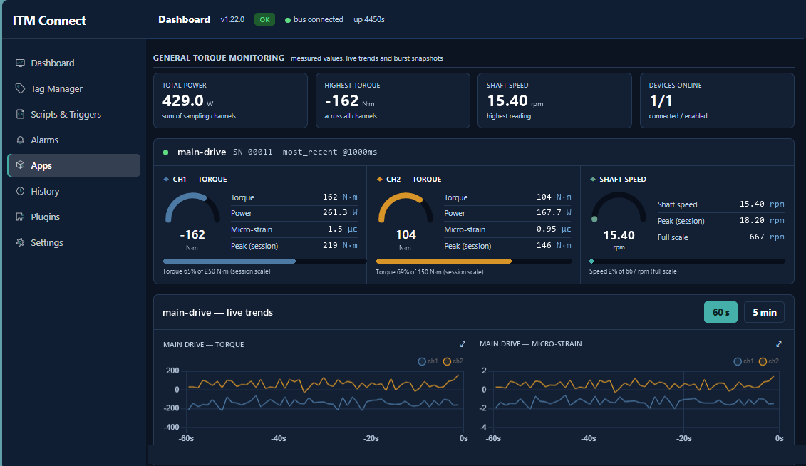
- Shows it live — gauges, trends and per-channel readouts for every transmitter, updated continuously, on one page in any browser on the network. Nothing to install on the viewing machine.
- Publishes it to ITM Connect — every measurement becomes a tag with the right units and engineering range already set, available to trending, alarms, the historian and every other connector on the platform. Add a transmitter and its tags are created for you.
- Records it — full-rate raw and calculated data written to TDMS, to local storage or a USB drive, with automatic space management. Recording never interrupts measurement.
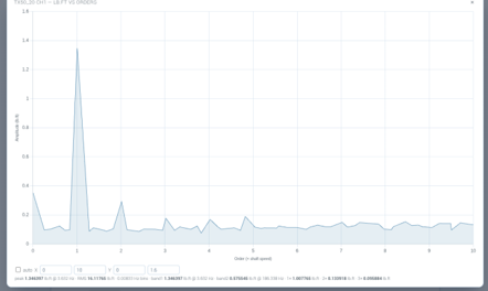
- High-speed capture — on a schedule you set, the transmitter switches to 2400 samples per second for a short window, enough resolution to see individual torsional events a continuous trend would average away.
- Frequency and order analysis — every captured window is shown as a spectrum with peak, RMS and named frequency bands, and, where shaft speed allows, in shaft orders using the speed the collar itself measures. No keyphasor, no export step.
- Transmitter health — battery, signal strength, packet counts and the transmitter’s own reported status, so a weak radio link or a battery approaching replacement is visible before it costs a measurement.
At a glance: 2 transmitters per system · 2 channels per transmitter · 2400 S/s sample rate · Bluetooth Low Energy · TDMS full-rate recording · FFT and shaft orders.
Order tracking is the differentiator. A torque collar on its own delivers a torque number. Order tracking turns the same collar into a diagnostic instrument: gear mesh, blade or pocket pass, coupling misalignment (order 2) and rotor eccentricity (order 1) each sit at a fixed, known order whatever the speed — so a developing fault can be recognised and trended without an analyst re-reading spectra every time the process changes speed. It runs at the edge, needs nothing on the shaft beyond the collar, and its results are tags: trendable, alarmable and available to the DCS.
TorqueTrak and the TT50 are products of Binsfeld Engineering Inc.
One shaft. Three measurements.
How the strain gauges are bonded to the shaft decides what the TT50 reports. The same collar, the same wireless link and the same app read torque, axial load or bending — so the question is not whether the shaft can be measured, but which load is costing you.
Torque
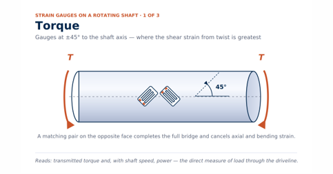
Twist puts the shaft surface in pure shear, and the principal strains lie at 45° to the axis. Gauges bonded at ±45° read that shear directly and reject the axial and bending strain a straight gauge would pick up. With shaft speed from the collar’s own gyro, torque becomes power.
Reads — transmitted torque and power: the true load through the driveline, not the motor’s electrical estimate.
Used on — propulsion shafts, gearbox input and output shafts, mill drives, agitators, pumps and fans, chip meters and screw feeders.
Axial (Thrust)
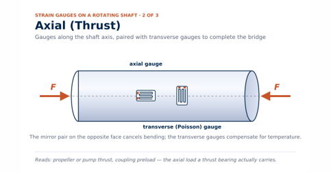
Thrust strains the whole cross-section evenly. Gauges bonded along the axis on opposite faces add the axial strain and cancel bending; transverse gauges complete the bridge and compensate for temperature. Each TT50 channel is configured for torque or for thrust, so one collar can carry both.
Reads — propeller or pump thrust, coupling preload: the axial load the thrust bearing actually carries.
Used on — marine propulsion shafts, vertical pump shafts, extruder and screw-press drives, thrust-bearing condition programs.
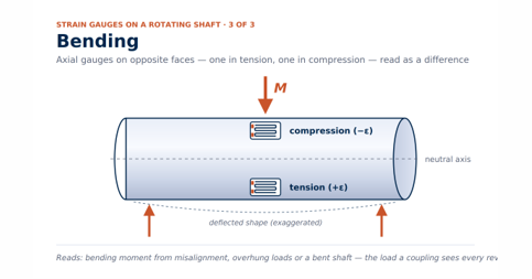
Bending
Bending stretches one side of the shaft and compresses the other. Axial gauges on opposite faces read equal and opposite strain; wired as a half or full bridge they double the bending signal and cancel axial load. On a turning shaft the bending strain cycles once per revolution — the fatigue load a coupling or bearing sees.
Reads — bending moment from misalignment, overhung loads or a bent shaft, resolved per revolution.
Used on — coupled drivelines after alignment work, overhung fans and blowers, roll necks and spindles, shafts with a suspected crack or bow.
“From Shaft to Cloud” program with Binsfeld Engineering; marine prop-shaft analytics reports in production.
Next step: start with a rental or one-off survey, then make it permanent.
Talk to an engineer: (844) 837-8797 · info@iTestSystem.com
Related Edge Solutions resources
-
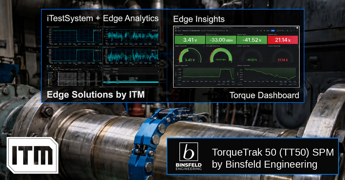
Torque-based Edge Insights: ITM iTestSystem Automated Analytics + Binsfeld TT50
In industrial and marine environments, the drivetrain is often the most critical — and least monitored — part of the system. Rotating shafts transferring torque through gearboxes, couplings, and propellers generate enormous forces that, left unmeasured, become the root cause of unexpected failures, unplanned downtime, and costly maintenance cycles. Traditional torque measurement solutions require shaft…
-
 Ash Hopper Monitoring, Boiler Monitoring, Condition Monitoring, Edge Solutions, Industrial Data Acquisition, industrial IoT, Industrial Monitoring, Power Plant Monitoring, Predictive Maintenance, Recovery Boiler, sootblower monitoring, Strain Gauge Monitoring, Thermocouple Monitoring, vibration monitoring, Wireless Monitoring
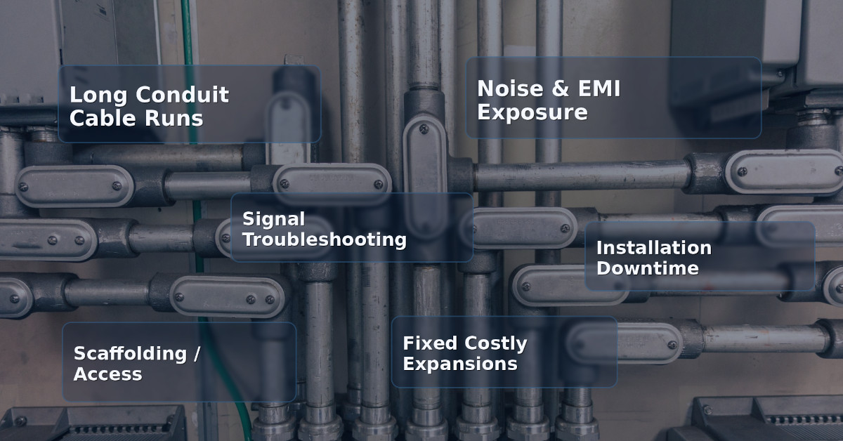
Hardwired vs. Wireless Industrial Monitoring: When Does Wireless Actually Make Sense?
For decades, hardwired data acquisition has been the default standard for industrial monitoring. From strain gauges on structural supports to thermocouples in recovery boilers, running conduit and pulling cable has been considered the “safe”…
-
 Boiler Efficiency, boiler safety, Edge Solutions, intelligent boiler cleaning, ITM monitoring systems, Predictive Maintenance, sootblower monitoring
Smarter Cleaning, Safer Boilers with ITM’s Monitoring Systems
The Business Case for ITM’s Sootblower Intelligent Maintenance and Fouling-Directed Cleaning Solutions Executive Summary Sootblowers are essential for keeping recovery, biomass, and power boilers clean and efficient. However, without proper monitoring and maintenance, they can become hidden sources of steam waste, mechanical failures, and even safety risks. Integrated Test and Measurement (ITM) has developed the…