Technical Details for using 120-ohm Strain Gauges with NI-9237 Modules and iTestSystem
Here’s a look at how we manage 120-ohm strain gages in a modern setup with the NI-9237 CompactDAQ module and iTestSystem.

Using a 120-ohm Strain Gauge with External Bridge Excitation in iTestSystem
3-Wire Quarter Bridge Completion
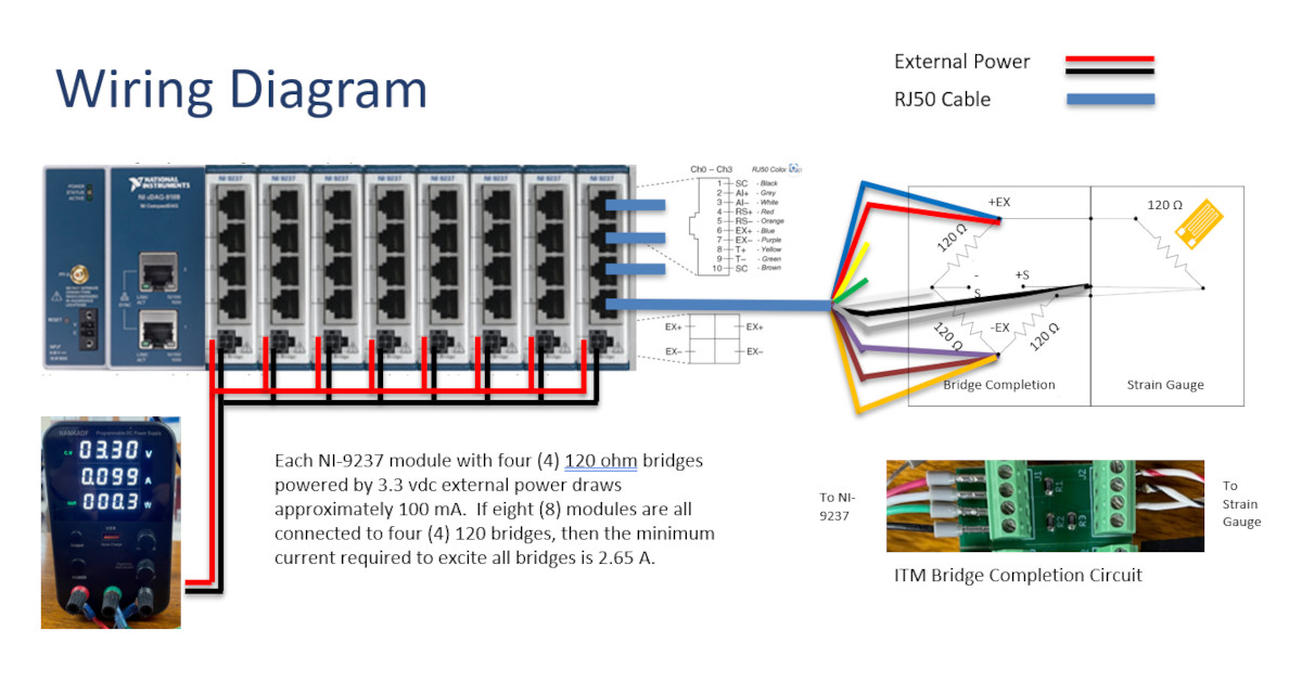
For a 120-ohm 3-wire quarter-bridge configuration, external bridge completion is critical. At ITM, we have built our own bridge completion circuit board for use in these situations. The NI-9237 requires an external circuit for quarter and half bridges.
NI-9237 Power Management
- The NI-9237 supplies 150 mW of internal power, which is sufficient for only two 120-ohm bridges when set to the lowest excitation voltage (2.5 V).
- By switching to external power (e.g., a 3.3 VDC supply), all four channels of the module can be used. This flexibility is essential when working with multi-channel setups.
Strain Calibration in iTestSystem
- Use the software’s “Calculator” function to determine the ShuntEq value (shunt equivalent resistance) for calibration verification. The NI-9237 contains an internal calibration resistor of 100 kΩ.
- The “Calculator” Requires that you enter the gage factor associated with the strain gage, Poisson ratio of the material being tested, and nominal resistance of the strain gage.
External Calibration with a Shunt Resistor
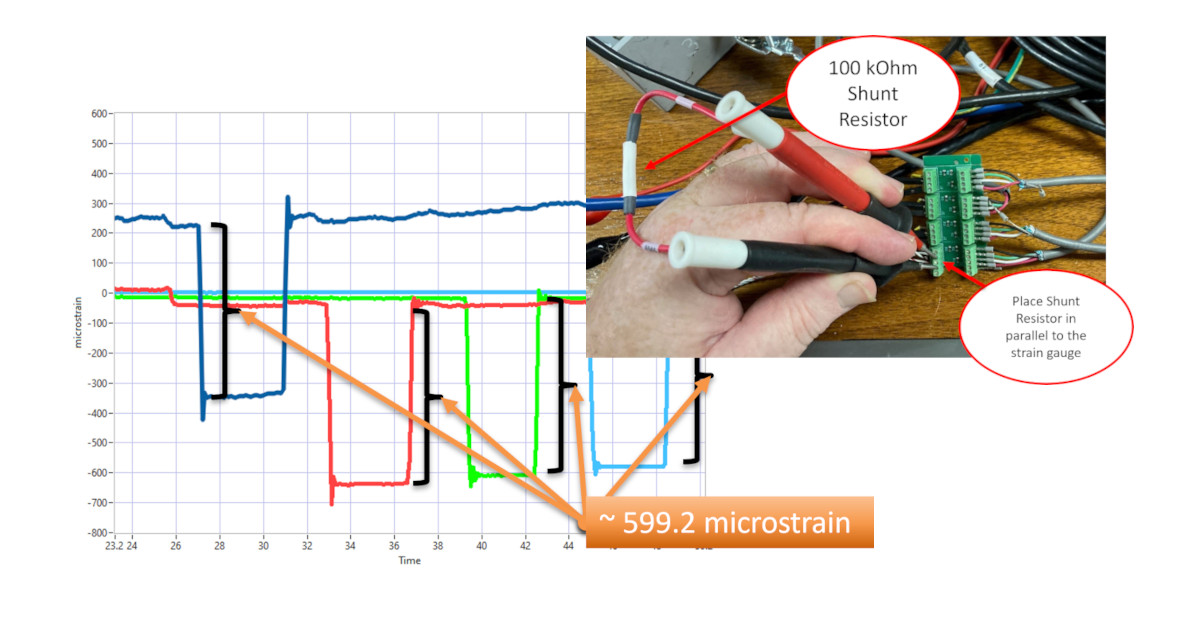
- To verify calibration, we placed a 100 kΩ external resistor in parallel with the installed strain gage. This causes an offset in the reading, which should match the calculated ShuntEq value (e.g., ~599.2 microstrain in one of our tests).
- This step ensures that the system is properly calibrated before data collection begins.

External Shunt Calibration
120-ohm Strain Gauge Data Collection
Once calibrated, create a DAQ task in the iTestSystem MultiDAQ application:
- Add the calibrated strain gage channels.
- Set the sample rate.
- Run the test.
During data collection, external shunt resistors can be applied again to verify calibration accuracy in real-time.
Why It Matters
Understanding the technical underpinnings of strain gages helps you make informed decisions about which configuration is best for your application. Whether you’re using a reliable 120-ohm gage or upgrading to higher resistance models, each choice comes with its own trade-offs and benefits.
At ITM, we’ve seen how proper configuration and calibration can make or break a test. Using tools like the NI-9237 and iTestSystem, we’ve streamlined the process of setting up, calibrating, and collecting data from strain gages, ensuring that you get reliable results every time.


 London, UK - May 19, 2023: The RL-10 liquid-fuel cryogenic rocket engine used on the Centaur, S-IV and DCSS upper stages, exposed at Science Museum of London, England, United Kingdom-Alfredo - stock.adobe.com