The most common strain gauge installation configuration is a 350 ohm, quarter bridge. Quarter bridge installations a generally the easiest and most economical installation for determining structural strain levels. In the quarter bridge configuration a single element strain gauge is mounted in the principle axial or bending strain direction.
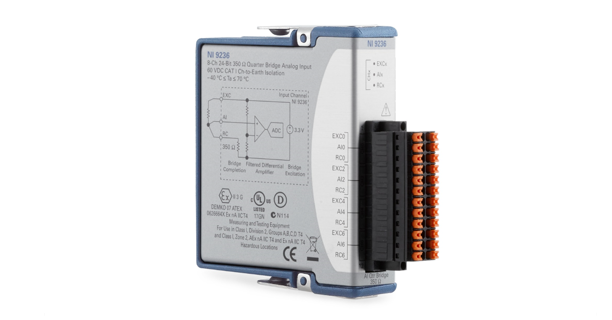
One tool that our engineers and technicians use to collect data from 350 ohm, quarter bridge strain gauge installations is the NI-9236 strain module. The NI-9236 is an 8-Channel C Series 350 ohm strain/bridge input module that is used with a CompactDAQ or CompactRIO chassis. This module provides bridge excitation (3.3 Volts), Wheatstone bridge completion, shunt calibration, and filtering for 350 ohm quarter bridges. Use this module in conjunction with a CompactDAQ chassis and iTestSystem engineering measurement software to collect synchronized, high-speed (10kHz) structure strain data.
The most common strain gauges used to quantify the state of stress on a test specimen’s surface, are uniaxial and rosette gauges. For accurate measurements of stress and strain, these uniaxial and rosette gauges are independently connected as a Wheatstone bridge in a 3-wire quarter-bridge or half-bridge arrangement.
Today, most high-end data acquisition equipment manufacturers provide signal conditioning options for collecting data from single strain gauges. Signal conditioning for strain gauges usually includes circuitry for bridge excitation voltage, quarter and half bridge completion arrangements, and shunt calibration.
What we offer
Are you looking for expert assistance with accurately measuring stress and strain? or, Do you need to rent or buy data acquisition equipment to collect stress and strain data?
Sometimes you may need to view or collect data from a single strain gauge using a device that only has analog voltage inputs and no strain signal conditioning. This was precisely the case when I was working with the HX711 load cell/strain amplifier. The HX711 requires a full bridge input so I instrumented my test specimens as such. If I needed to use a single strain gauge with the HX711, I would have had to use an external bridge completion circuit.
What are your options for measuring single strain gauges with a device that only has voltage inputs or full bridge inputs?
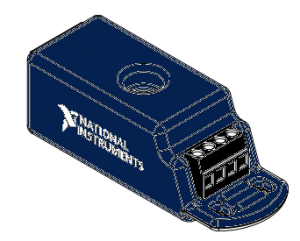
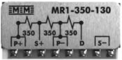
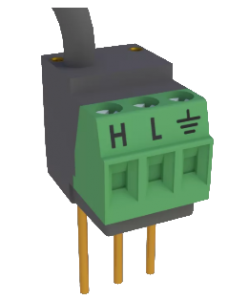
Option 1: Buy a commercial off the shelf bridge completion modules.
The list below gives the specifications for some available bridge completion modules. I plan on adding more completion modules to this list for future reference, so send me any additional completion options.
If you are building a product or are in the strain business long term, building your own circuit may be a cost effective alternative to the potentially more expensive off the shelf bridge completion option. I have built a few bridge completion circuits in the past. Here is a list of things to keep in mind when designing a circuit.
Use high precision, low resistance temperature coefficient resistors
The voltage source used for bridge excitation should be from a stable source like a reference since the output of a Wheatstone bridge is inversely proportional to the excitation voltage Vout/Vex.
Use remote sensing to compensate for errors in excitation voltage from long lead wires
Amplification will increase measurement resolution and improve signal-to-noise ratio
Filter data to remove external, high-frequency noise
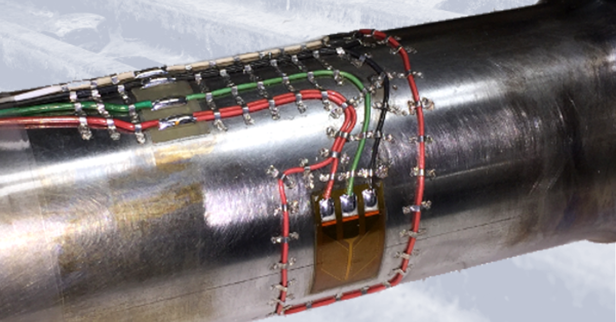
Image1: Shaft torque strain gauge installation example for field testing
Our engineers and technicians have epoxied, soldered and spot welded strain gauges for applications ranging from high temperature exhaust systems to miniature load cell measurements. Every application requires a unique understanding of the strain measurement requirements including installation environment.
If the strain gauge installation is to survive in the field you must plan for the conditions it will undergo. Three important variables that you should account for are temperature range, liquid exposure, and potential impact forces. These variables determine the type of strain gauge, epoxy, solder, wiring, coating, and impact/wear protection to use in the application. The table below shows which variables affect your installation choices.
Gauge
Epoxy
Solder
Wiring
Coating
Covering
Temperature
Liquid Exposure
Impact Forces
Table1: Strain gauge installation variables
For more information about ITM’s strain gauging services contact Ryan Welker at email: ryan.welker@itestsystem.com or phone: 1.844.837.8797 x702
https://itestsystem.com/wp-content/uploads/2019/09/Shaft-Torque1200x628.png6281200Ryan Welkerhttps://itestsystem.com/wp-content/uploads/2020/05/itmlogo_Horizontal_3x1.pngRyan Welker2019-09-13 18:01:532023-08-03 00:43:20Strain Gauge Installations for Field Testing
We use cookies to ensure that we give you the best experience on our website. If you continue to use this site we will assume that you are happy with it.