Strain Gauging Services

The strain gauge services category contains posts that describe ITM’s strain gauging services and applications.

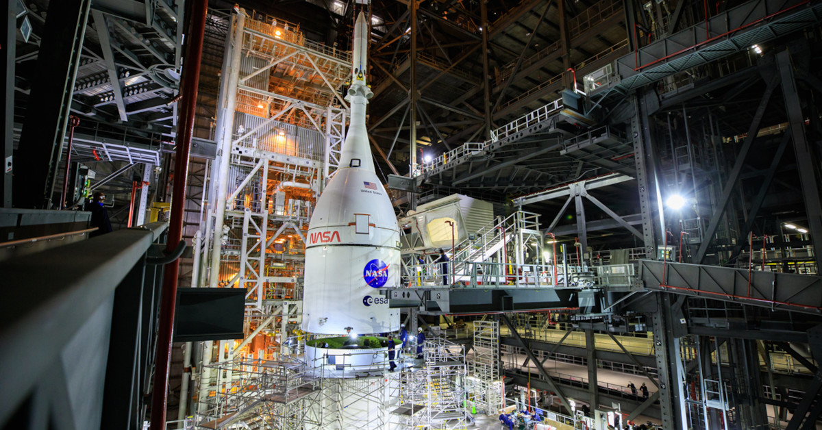
ITM Engineers Strain Gauge in Shadow of Artemis I Rocket Launch


Engineers Test Orion Spacecraft

Engineers Test Artemis I Spacecraft Orion at Johnson Space Center


ITM strain gauge team witnesses powerful forces during two-week trip to Cape Canaveral

A group of engineers and aerospace engineering technicians from Integrated Test & Measurement just returned after an unforgettable experience in Cape Canaveral.

ITM’s team was there to assist an aerospace engineering partner with on-site strain gauging. The challenge was to assist in validating rocket components ahead of an upcoming launch, which required completing a massive strain gauge instrumentation project.

ITM’s team was there to assist an aerospace engineering partner with on-site strain gauging. The challenge was to assist in validating rocket components ahead of an upcoming launch, which required completing a massive strain gauge instrumentation project.

The team’s work was delayed due to Hurricane Nicole, so they waited out the storm just blocks from the beach, said Ryan “RJ” Matthews, ITM engineer. As powerful as it was seeing a storm with wind speeds exceeding 130 mph, the hurricane was still a distant second in the most memorable department to their up-close view of NASA’s Artemis I mission rocket launch.

Matthews said the team took a break from strain gauging a rocket booster, an intense project that required a significant amount of cable routing, to observe the launch from just a few miles away.

To accommodate their partner, ITM’s crew worked eight 12-hour shifts from 5 p.m. to 5 a.m., so perfect timing to watch NASA take a first step toward blazing a path back to the Moon in the early hours of Nov. 16.

About 45 minutes after the anticipated launch time, fireball from the SLS Rocket lit up the night sky.

Artemis I Rocket Launch Time Lapse

Artemis I SLS Rocket Launch Time Lapse

“It was incredible,” said Matthews, who witnessed the launch from a balcony. “It was super bright — kind of like a 1-minute sunrise. About 40 seconds later, it started rattling the building.”

Contact us for more information about our aerospace, strain gauging and testing services.

Engineering Data Acquisition Tools: NI-9237 Bridge Input Module


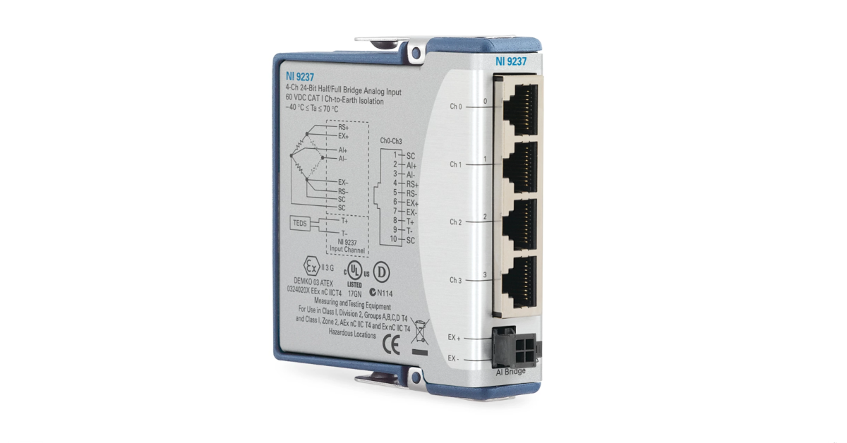
For bridge type sensors and most strain gauges configurations (full and half bridges), our engineers will opt for the NI-9237 C-Series module to acquire strain and bridge data instead of the NI-9235 or NI-9236 modules.  Unlike the NI-9236 module, the NI-9237 can acquire data from:

  • Any resistance strain gauge (not just 120 or 350 Ohm)
  • Quarter, half, and full-bridge strain gauge configurations
  • Torque and load cells (off-the-shelf and custom)

The NI-9237 is a 4-Channel C Series strain/bridge input module that contains circuitry to power, scale and calibrate strain and load sensors .  For quarter and some half bridge measurements a bridge completion module must be used in conjunction with this module. The NI-9237 module provides internal bridge excitation (2.5V, 3.3V, 5V, or 10V) and shunt calibration resistors for sensor scaling verification. To collect synchronized and scaled high-speed (50kHz) structure strain and load cell data, use our iTestSystem engineering measurement software.

For more information about the NI-9237, DAQ module rental, strain gauge installations or our data logging solution iTestSystem, contact Ryan Welker via email: ryan.welker@itestsystem.com or phone: (844) 837-8797 x706.

Engineering Data Acquisition Tools: NI-9236 Strain Module

NI-9236 Strain Gauge Module

The most common strain gauge installation configuration is a 350 ohm, quarter bridge.  Quarter bridge installations a generally the easiest and most economical installation for determining structural strain levels.  In the quarter bridge configuration a single element strain gauge is mounted in the principle axial or bending strain direction.

One tool that our engineers and technicians use to collect data from 350 ohm, quarter bridge strain gauge installations is the NI-9236 strain module.  The NI-9236 is an 8-Channel C Series 350 ohm strain/bridge input module that is used with a CompactDAQ or CompactRIO chassis.  This module provides bridge excitation (3.3 Volts), Wheatstone bridge completion, shunt calibration, and filtering for 350 ohm quarter bridges.  Use this module in conjunction with a CompactDAQ chassis and iTestSystem engineering measurement software to collect synchronized, high-speed (10kHz) structure strain data.

For more information about the NI-9236, DAQ module rental, strain gauge installations or our data logging solution iTestSystem, contact Ryan Welker via email: ryan.welker@itestsystem.com or phone: (844) 837-8797 x702

Strain Gauge Bridge Completion Modules

350 Ohm Quarter Bridge Strain Completion

Quarter Strain Bridge with Completion Circuit

The most common strain gauges used to quantify the state of stress on a test specimen’s surface, are uniaxial and rosette gauges.  For accurate measurements of stress and strain, these uniaxial and rosette gauges are independently connected as a Wheatstone bridge in a 3-wire quarter-bridge or half-bridge arrangement.

Strain Gauge Installations for Field TestingStrain Gauge Servicestshirt-Strain Gauge Services Rectangular RosetteEngineering Data Acquisition Tools: NI-9237 Bridge Input Module

Custom PTO Shaft Strain Gauge Transducer by ITMCustom Strain Transducer ServiceCustom Strain Gauge Measures KitchenAid Shaft Load

Today, most high-end data acquisition equipment manufacturers provide signal conditioning options for collecting data from single strain gauges.  Signal conditioning for strain gauges usually includes circuitry for bridge excitation voltage, quarter and half bridge completion arrangements, and shunt calibration.

What we offer

Are you looking for expert assistance with accurately measuring stress and strain? or, Do you need to rent or buy data acquisition equipment to collect stress and strain data? 

Sometimes you may need to view or collect data from a single strain gauge using a device that only has analog voltage inputs and no strain signal conditioning.  This was precisely the case when I was working with the HX711 load cell/strain amplifier.  The HX711 requires a full bridge input so I instrumented my test specimens as such.  If I needed to use a single strain gauge with the HX711, I would have had to use an external bridge completion circuit.

What are your options for measuring single strain gauges with a device that only has voltage inputs or full bridge inputs?

Option 1: Buy a commercial off the shelf bridge completion modules.

The list below gives the specifications for some available bridge completion modules.  I plan on adding more completion modules to this list for future reference, so send me any additional completion options.

Strain Gauge Completion Modules
 
Manufacturer NI VPG Campbell Scientific
Model # NI 9926, NI 9945, NI 9944 MR1-10C-129, MR1-350-130, MR1-120-133 4WFBS1K, 4WFBS350, 4WFBS120
Description 3-Wire Quarter Bridge Completion 3-Wire Quarter Bridge Completion 3-Wire Quarter Bridge Completion
Resistance 1000 Ω, 350 Ω, 120 Ω 1000 Ω, 350 Ω, 120 Ω 1000 Ω, 350 Ω, 120 Ω
Strain Gauge Connector Terminal Block Solder Tab Terminal Block
Device Connector RJ50 Solder Tab Pins and Lead Wire

Option 2: Build your own circuit.

If you are building a product or are in the strain business long term, building your own circuit may be a cost effective alternative to the potentially more expensive off the shelf bridge completion option.  I have built a few bridge completion circuits in the past.  Here is a list of things to keep in mind when designing a circuit.

  1. Use high precision, low resistance temperature coefficient resistors
  2. The voltage source used for bridge excitation should be from a stable source like a reference since the output of a Wheatstone bridge is inversely proportional to the excitation voltage Vout/Vex.
  3. Use remote sensing to compensate for errors in excitation voltage from long lead wires
  4. Amplification will increase measurement resolution and improve signal-to-noise ratio
  5. Filter data to remove external, high-frequency noise

For more information about bridge completion or our strain gauging services, contact Ryan Welker @ (844) 837-8797 x701.

Related Links

Strain Gauge Installations for Field Testing

iTestSystem Tip: Strain Gauge Rosette Analysis

Wireless Strain Measurements with iTestSystem, LabVIEW, and Arduino

Ohio University Asphalt Cracking Prediction System Project

Strain Gauge Installations for Field Testing

shaft torque sensor

Image1: Shaft torque strain gauge installation example for field testing

Our engineers and technicians have epoxied, soldered and spot welded strain gauges for applications ranging from high temperature exhaust systems to miniature load cell measurements. Every application requires a unique understanding of the strain measurement requirements including installation environment.

If the strain gauge installation is to survive in the field you must plan for the conditions it will undergo. Three important variables that you should account for are temperature range, liquid exposure, and potential impact forces. These variables determine the type of strain gauge, epoxy, solder, wiring, coating, and impact/wear protection to use in the application. The table below shows which variables affect your installation choices.

  Gauge Epoxy Solder Wiring Coating Covering
Temperature  
Liquid Exposure      
Impact Forces      

Table1: Strain gauge installation variables

For more information about ITM’s strain gauging services contact Ryan Welker at email: ryan.welker@itestsystem.com or phone: 1.844.837.8797 x702