High Channel Count Synchronous Datalogging
From edge to AWS cloud, ITM’s iTestSystem turns massive datalogging into actionable KPIs, enabling operators to monitor usage and structural health instantly.

From edge to AWS cloud, ITM’s iTestSystem turns massive datalogging into actionable KPIs, enabling operators to monitor usage and structural health instantly.
Obvious signs of fatigue — cracks at the corners of doors — had begun to surface on an in-service Railcar. A railcar structural testing case study.
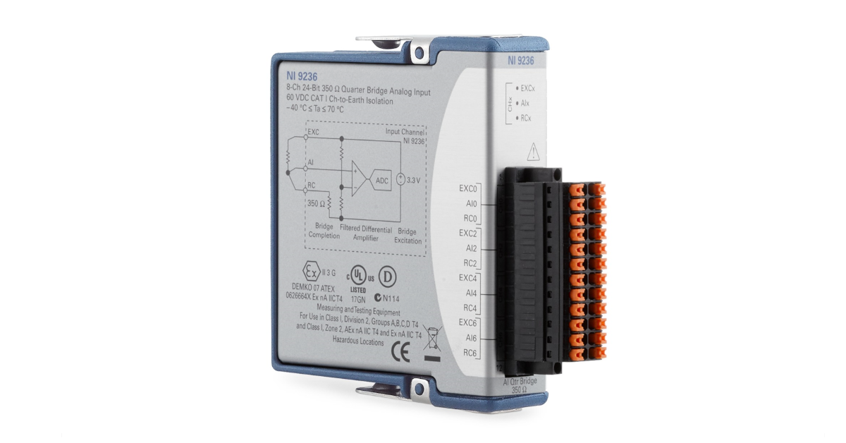
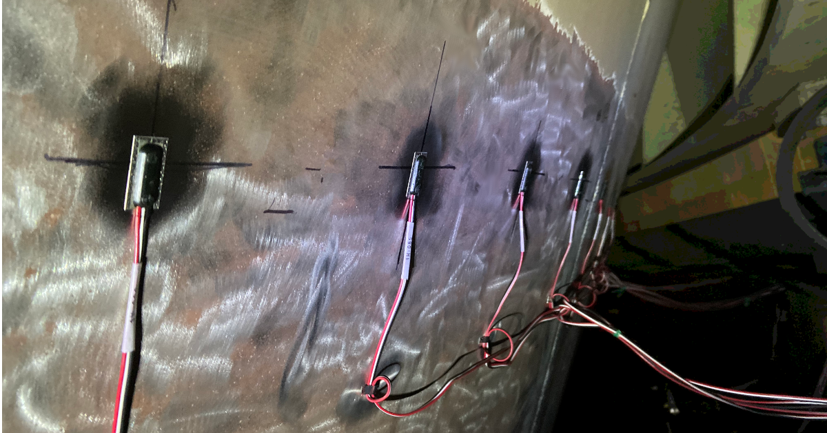
The most common strain gauge installation configuration is a 350 ohm, quarter bridge. Quarter bridge installations a generally the easiest and most economical installation for determining structural strain levels. In the quarter bridge configuration a single element strain gauge is mounted in the principle axial or bending strain direction.
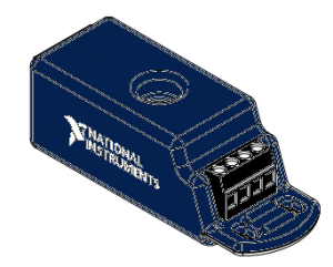
One tool that our engineers and technicians use to collect data from 350 ohm, quarter bridge strain gauge installations is the NI-9236 strain module. The NI-9236 is an 8-Channel C Series 350 ohm strain/bridge input module that is used with a CompactDAQ or CompactRIO chassis. This module provides bridge excitation (3.3 Volts), Wheatstone bridge completion, shunt calibration, and filtering for 350 ohm quarter bridges. Use this module in conjunction with a CompactDAQ chassis and iTestSystem engineering measurement software to collect synchronized, high-speed (10kHz) structure strain data.
For more information about the NI-9236, DAQ module rental, strain gauge installations or our data logging solution iTestSystem, contact Ryan Welker via email: ryan.welker@itestsystem.com or phone: (844) 837-8797 x702
Check out this video showing one of our custom rugged data acquisition systems! We provide custom systems like this for aerospace, vehicle, off-highway, and civil applications. This system shown in this video was designed for collecting strain, vibration, and other sensors on a civil structure.
For more information about our testing services and custom test systems, contact Ryan Welker via email: ryan.welker@itestsystem.com or phone (844) 837-8797 x702
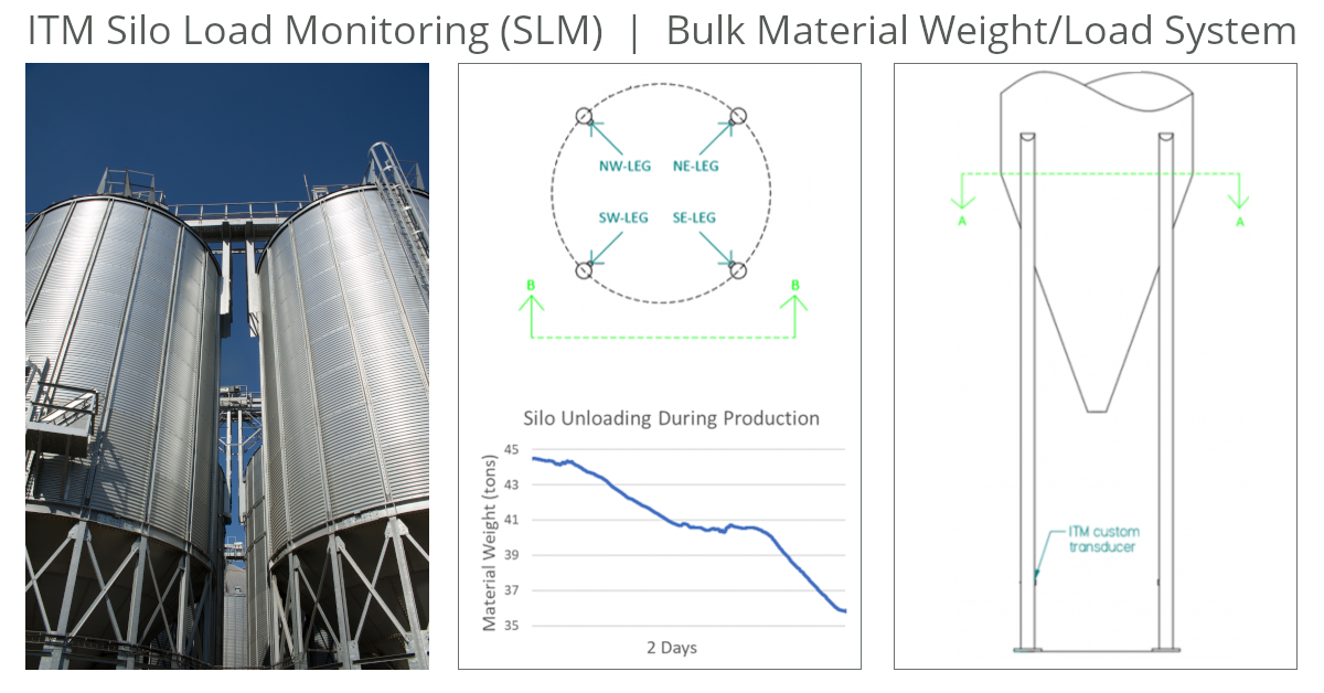
Plant operators need to continuously measure bulk material levels/weight in their silos and hoppers to ensure their processes are running safely, efficiently, and without bottlenecks. Measuring these levels allows operators to automate vessel filling, verify material consumption, and prevent overfilling.
ITM provides its customers with a variety of structural load monitoring systems. Using strain gauge based transducer technology, ITM can design and implement a real-time system to continually monitor load responses of the supporting members on an array of structures.
Strain gauge based measurements are more accurate and typically less expensive than load cell retrofitting. The addition of a monitoring system can also reduce the risks associated with manual measurements including contamination of product and, more importantly, injury to a worker.
The two ways to measure bulk material quantity in silos/hoppers are level indicators (laser, ultrasonic, radar) and weight measurements (load cells, strain gauges). Weight measurements are more accurate, safer to install, and can be installed during operation. Of the types of weight measurements, ITM prefers to implement strain gauge-based solutions since they do not require structural modification of the vessel.
An ITM silo monitoring system typically consists of weatherproofed strain gauges for each silo leg and a NI CompactRIO embedded controller to acquire data, process signals, and output results. Systems are scalable to accommodate all the silos at the plant.
The graph above shows a typical trend of real silo data during unloading. Weight levels are sent directly to factory DCS systems and historians via common communication protocols like Ethernet/ip and Modbus, or they can be viewed on the system’s webpage or a local/remote workstations and panels.
Most bulk material storage is outside, so temperature and other environmental factors must be accounted for not only in the durability of the equipment, but in the sensor design and data processing. Changes in temperature, wind, and humidity can result in changes to the load path in silo legs. Load changes are account for by instrumenting all or most of the silo legs and selecting the appropriate strain gauge bridge design which results in continuously accurate weight measurements.
While other systems require calibrating the system with known loads (point calibration), ITM calibrates the system using a shunt voltage across the strain gauge bridge. This process automatically calibrates the system and eliminates the requirement of having pre-known material weight added to the vessel.
For more information about silo monitoring, contact Ryan Matthews @ 1.844.837.8797 x706. To see how ITM’s structural load monitoring systems work watch this video below.
At ITM, we understand that our customers do not settle for good enough. When it comes to measuring and capturing data for real-world applications and structural analysis, you cannot compromise, so neither can we. Instead of having to pick and choose the most critical locations to measure, we ensure that you can capture every piece of data you need, simultaneously. Whether that is a single strain bridge, or thousands of strain channels, we make your data logging project a success.
On past projects, we have worked with our customers in the manufacturing industry to test the structures of their aerospace, mining, construction and other transportation equipment. Some of these applications not only needed to collect strain, vibration, voltage, and other signals simultaneously but also required well over a thousand total sensor channels. Network synchronization technology embedded within the NI cDAQ chassis allow users to account for the sheer number of channels during these structural tests. The true secret to our success in these high-channel jobs has been our iTestSystem software which leverages the cDAQ’s synchronization technology while providing an intuitive data acquisition and sensor configuration and setup.
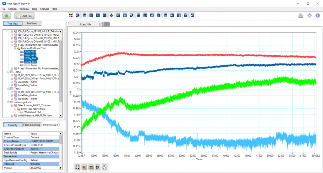
iTestSystem is far more than just a barebones data collection software. It can be a time saver to our engineers by helping to sort channels, keep various tasks organized, and even provide an easy and quick way to view results with the integrated TestView Plus Application (shown below).
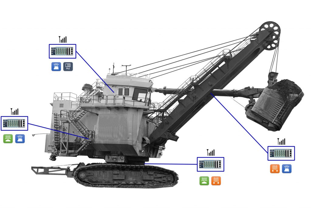
The mining shovel pictured below, which is similar to other equipment that ITM has instrumented in the past, illustrates a distributed data acquisition system for collecting data. Using iTestSystem, we can implement a modified tree synchronization topology to collect data from over 20+ cDAQ chassis simultaneously. Data can be collected in one giant file containing all sensor channels or saved into separate files based on location. In past projects, we saved over 1000 channels from strain, acceleration, and voltage sensors into a new file every 10 minutes. We added the sensor location to the sensor description, including the Boom, Operator Cab, Main Frame and Base. This allowed us to easily sort data both during and after the collection.
Our goal at Integrated Test & Measurement is to provide efficient testing solutions and services to address your company’s needs. If you need to measure high channel counts, or have questions about our rugged DAQ systems, software, rental equipment or testing services, then please contact ITM by phone or e-mail.
Contact Information: For more information on this Article, please visit iTestSystem.com or contact: Ryan Welker – Integrated Test & Measurement (ITM), LLC – ryan.welker@itestsystem.com or (844) 837-8797
Our test engineers are often called upon to deploy unattended or “black box” data acquisition systems in the field. These systems are deployed on machinery, vehicles, and industrial processes to constantly record strain and vibration data at sample rates between 100 and 100,000 Hz. That adds up to a lot of data to sift through.
In situations where we are trying to identify system operation outliers or damaging events, we utilize the Automated Analytics application in iTestSystem to limit the amount of data searches required. The Automated Analytics application allows users to analyze, build, and send sensor level reports only when specific vibration and strain limits are exceeded. Instead of searching through data files, engineers can easily review the report and download relevant data files from deployed systems for further analysis.
This video demonstrates how to build and send vibration and strain reports using Automated Analytics and other iTestSystem tools and applications.
For more information about our iTestSystem or ITM’s testing services, contact Ryan Welker @ (844) 837-8797 x702.
Related Links
When it comes to measuring structural stresses and load, every application is unique, and sometimes that means using a different solution. In some cases where strain gauges are applied, it can be advantageous or even necessary to use weldable strain gauges instead of chemical bonding the strain gauges to the specimen.
Since many epoxies used to chemically bond strain gauges require specific heat and pressure for curing, it can be difficult or even impossible to use this method on large or irregular structures. Weldable strain gauges offer an advantage in this situation as they eliminate the need to clamp and cure any epoxies for bonding. In addition, weldable gauges can be installed in a variety of environments and weather conditions which offers additional advantages over traditionally bonded strain gauges. Although weldable strain gauges are applied differently, they function in much the same way as their bondable counterparts.
To properly install a weldable strain gauge, you will need:
Always remember to have the proper safety equipment on hand, such as eye protection and gloves, as well as any PPE required by your environment.
When installing a weldable strain gauge, you must first prep the area. Unlike bondable gauges, the area does not need to be polished to a fine degree. Simply degrease the gauge area, sand down any paint, coatings or excess debris and ensuring the area is purely metallic and free of chemicals is enough. A clean metal surface is important to the welding process.
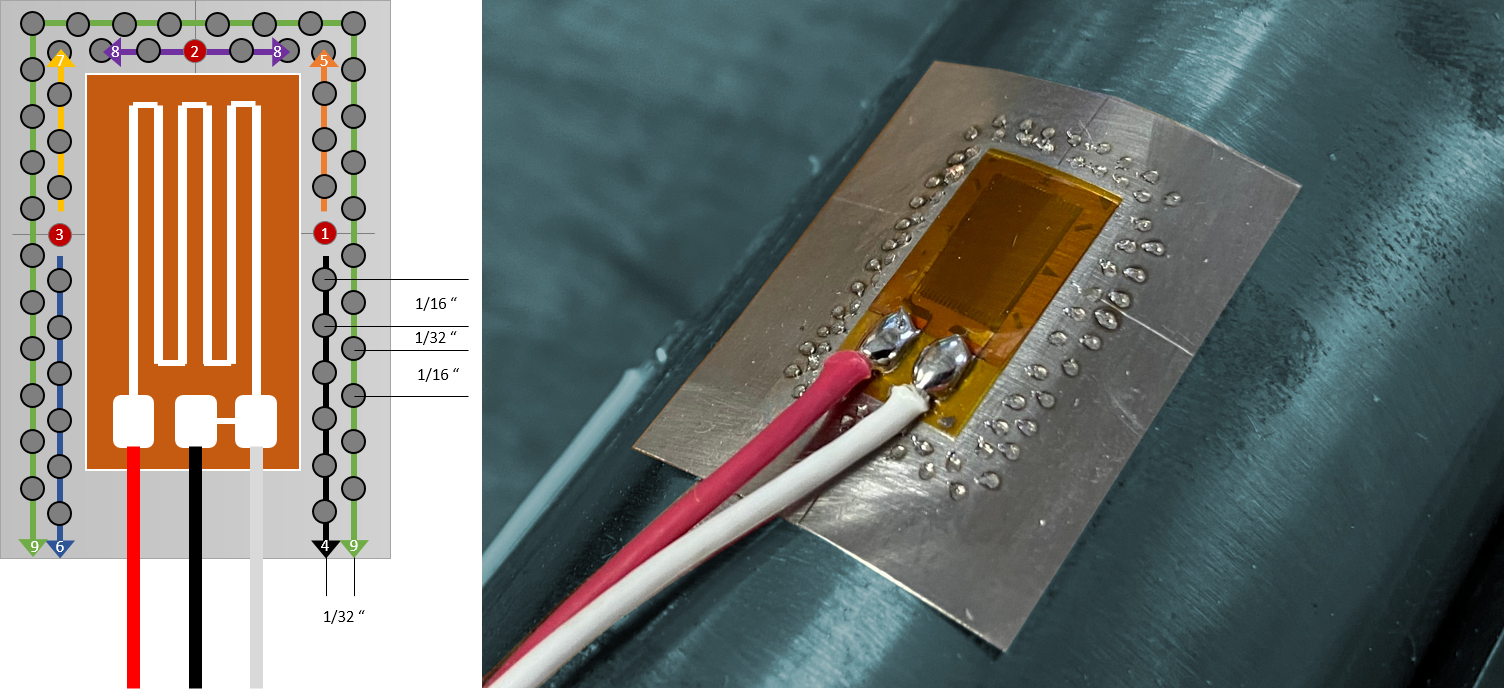
After the part has been cleaned, you can position the gauge. Most weldable gauges come marked so you can align the grid properly. When the gauge is properly aligned, spot weld the gauge on either side of the gauge along the centerlines, to hold it firmly in position and prevent shifting as the gauge is welded further. Once secure, the gauge should be welded all around the carrier surface, as illustrated below.
Recap:
For more information about our strain gauging and testing services, contact Ryan Welker @ (844) 837-8797 x702.
Related Links

Quarter Strain Bridge with Completion Circuit
The most common strain gauges used to quantify the state of stress on a test specimen’s surface, are uniaxial and rosette gauges. For accurate measurements of stress and strain, these uniaxial and rosette gauges are independently connected as a Wheatstone bridge in a 3-wire quarter-bridge or half-bridge arrangement.
Strain Gauge Installations for Field Testing | Strain Gauge Services | tshirt-Strain Gauge Services Rectangular Rosette | Engineering Data Acquisition Tools: NI-9237 Bridge Input Module
Custom PTO Shaft Strain Gauge Transducer by ITM | Custom Strain Transducer Service | Custom Strain Gauge Measures KitchenAid Shaft Load
Today, most high-end data acquisition equipment manufacturers provide signal conditioning options for collecting data from single strain gauges. Signal conditioning for strain gauges usually includes circuitry for bridge excitation voltage, quarter and half bridge completion arrangements, and shunt calibration.
Are you looking for expert assistance with accurately measuring stress and strain? or, Do you need to rent or buy data acquisition equipment to collect stress and strain data?
Sometimes you may need to view or collect data from a single strain gauge using a device that only has analog voltage inputs and no strain signal conditioning. This was precisely the case when I was working with the HX711 load cell/strain amplifier. The HX711 requires a full bridge input so I instrumented my test specimens as such. If I needed to use a single strain gauge with the HX711, I would have had to use an external bridge completion circuit.
Option 1: Buy a commercial off the shelf bridge completion modules.
The list below gives the specifications for some available bridge completion modules. I plan on adding more completion modules to this list for future reference, so send me any additional completion options.
 |
 |
 |
|
| Manufacturer | NI | VPG | Campbell Scientific |
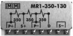
| Model # | NI 9926, NI 9945, NI 9944 | MR1-10C-129, MR1-350-130, MR1-120-133 | 4WFBS1K, 4WFBS350, 4WFBS120 |
| Description | 3-Wire Quarter Bridge Completion | 3-Wire Quarter Bridge Completion | 3-Wire Quarter Bridge Completion |
| Resistance | 1000 Ω, 350 Ω, 120 Ω | 1000 Ω, 350 Ω, 120 Ω | 1000 Ω, 350 Ω, 120 Ω |
| Strain Gauge Connector | Terminal Block | Solder Tab | Terminal Block |
| Device Connector | RJ50 | Solder Tab | Pins and Lead Wire |
Option 2: Build your own circuit.
If you are building a product or are in the strain business long term, building your own circuit may be a cost effective alternative to the potentially more expensive off the shelf bridge completion option. I have built a few bridge completion circuits in the past. Here is a list of things to keep in mind when designing a circuit.
For more information about bridge completion or our strain gauging services, contact Ryan Welker @ (844) 837-8797 x701.
Related Links
Strain Gauge Installations for Field Testing
iTestSystem Tip: Strain Gauge Rosette Analysis
Wireless Strain Measurements with iTestSystem, LabVIEW, and Arduino

ITM provides software development, structural and mechanical testing services, industrial monitoring, strain gauging, and data analysis solutions to clients on six continents. ITM is a recognized National Instruments Gold Alliance Partner.
![]()