
Tag Archive for: vibration
In Vehicle Vibration Testing
building a rugged and flexible in-vehicle testing solution to measure the vibration levels.
Sound & Vibration DAQ Tools: NI-9231 Module
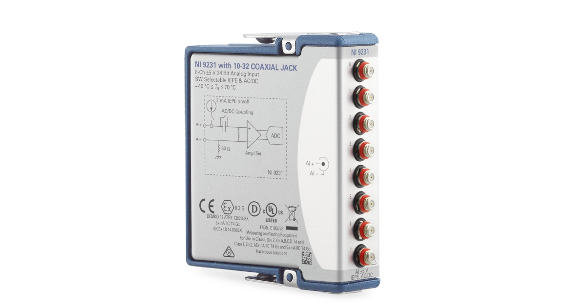
When measuring noise and vibration levels, our engineers use the NI-9231 sound and vibration module, a CompactDAQ chassis and a Laptop running iTestSystem for data logging and analysis. The NI-9231 module is an updated, higher channel count version of the NI-9234 module.
The NI-9231 is an 8 channel, 51.2 kS/s/channel, -5 V to 5 V, C Series Input Module with IEPE excitation that can be turned on and off, and open/short circuit detection. To increase channel capacity, these modules use 10-32 plug for its sensor input connections. NI provides a PCB Low Noise Coaxial Cable, 10 ft w/10-32 plug to BNC plug to accommodate most standard accelerometer and microphone connections.
For more information about doing data collection with the NI-9231, iTestSystem or sound and vibration measurements, contact Ryan Welker via email: ryan.welker@itestsystem.com or phone: (844) 837-8797 x702
Video: Custom Rugged Data Acquisition Systems
Check out this video showing one of our custom rugged data acquisition systems! We provide custom systems like this for aerospace, vehicle, off-highway, and civil applications. This system shown in this video was designed for collecting strain, vibration, and other sensors on a civil structure.
For more information about our testing services and custom test systems, contact Ryan Welker via email: ryan.welker@itestsystem.com or phone (844) 837-8797 x702
Structural Validation & Testing of Generator Sets
A case study describing a reliable system for testing generator vibration levels after production in order to verify proper unit design and assembly.
Vibration and Strain Gauge Level Report Automation with iTestSystem
Our test engineers are often called upon to deploy unattended or “black box” data acquisition systems in the field. These systems are deployed on machinery, vehicles, and industrial processes to constantly record strain and vibration data at sample rates between 100 and 100,000 Hz. That adds up to a lot of data to sift through.
In situations where we are trying to identify system operation outliers or damaging events, we utilize the Automated Analytics application in iTestSystem to limit the amount of data searches required. The Automated Analytics application allows users to analyze, build, and send sensor level reports only when specific vibration and strain limits are exceeded. Instead of searching through data files, engineers can easily review the report and download relevant data files from deployed systems for further analysis.
This video demonstrates how to build and send vibration and strain reports using Automated Analytics and other iTestSystem tools and applications.
For more information about our iTestSystem or ITM’s testing services, contact Ryan Welker @ (844) 837-8797 x702.
Related Links
Accelerometers for Rotating Machinery Vibration Measurements
Choosing an accelerometer for rotating machinery vibration measurements can be a daunting task since there are so many options available. This blog outlines the characteristics you should consider when choosing a piezoelectric single axis accelerometer for general purpose vibration measurements and presents some accelerometers to consider.
Characteristics of a General Purpose Accelerometer
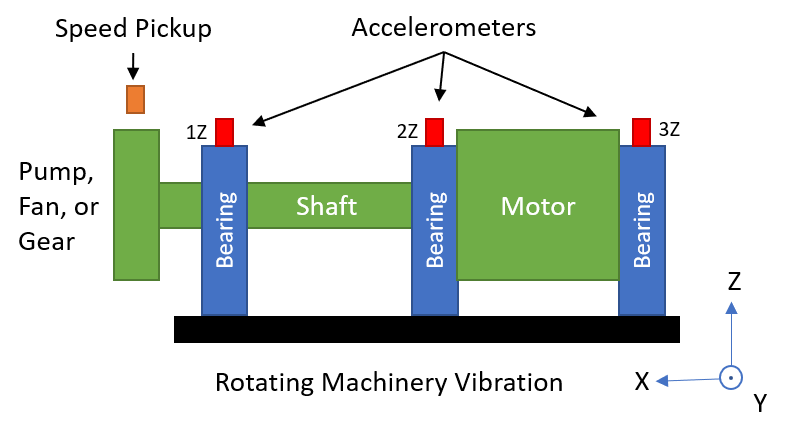
When measuring vibration on rotating equipment such as motors, pumps, and generators, the most common measurement location(s) are on the shaft bearing housing(s) at the shaft centerline. At this location, typical vibration levels perpendicular to the shaft are < 100 g and the frequency range of interest is < 5000 Hz. A general purpose single axis piezoelectric accelerometer with either a 10 mV/g or 100 mV/g sensitivity fits this criteria.
Other characteristics to consider are size, mounting options, cable connections, grounding, and cost. Several mounting options are available. They include magnetic bases, adhesive bases and stud mounts. The mounting option you choose affects the frequency range of your accelerometer measurements. The table below shows typical frequency limits for accelerometer mounting methods.
| Mount Type | Typical Frequency Limit |
| Magnet | 2,000 Hz |
| Adhesive | 5,000 Hz |
| Stud | 6,000 Hz |
5 General Purpose Accelerometers
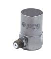
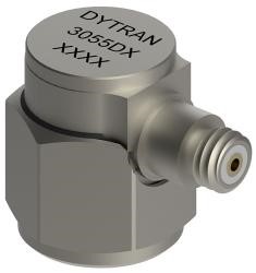
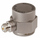
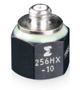
The table below shows some examples of stud mounted general purpose piezoelectric accelerometers. These accelerometers all have a female 10-32 coaxial / microdot connector. It is important to note that this is not a complete list of accelerometers and there are many options available from each manufacturer. I would encourage you to go to the websites linked in the table and see what’s available.
 |
 |
 |
 |
 |
|
| Manufacturer | PCB | Dytran | BRÜEL & KJÆR | Endevco | Kistler |
| Model # | 353B03 | 3055D1 | 4533-B | 256HX -10 | 8702B500-M1 |
| Sensitivity | 10 mV/g | 10 mV/g | 9.8 mV/g | 10 mV/g | 10 mV/g |
| Frequency Range | (±5%) 1 to 7000 Hz | (±5%) 1 to 5000 Hz | (±10%) 0.2 – 12800 Hz | (±10%) 1 to 10000 Hz | (±5%) 1-10000 Hz |
| Temperature Range | -65 to +250 °F | -67 to +250 °F | –67 to +257 °F | -67˚F to +257˚F | -67˚F to +257˚F |
| Height | 0.88 in | 0.64 in | 0.54 in | 0.55 in | 0.67 in |
| Weight | 0.38 oz | 0.35 oz | 0.3 oz | 0.14 oz | 0.32 oz |
| Housing Material | Titanium | Titanium | Titanium | Titanium | Titanium |
| Electrical Connector | 10-32 Coaxial (side) | 10-32 Coaxial (side) | 10–32 Coaxial (side) | 10–32 Coaxial (top) | 10–32 Coaxial (side) |
| Mounting Thread | 10-32 Female | 10-32 Female | 10-32 Female | 10-32 Female | 10-32 Female |
For more information about collecting vibration data, accelerometers, iTestSystem, or test equipment rental, contact Mark Yeager @ (844) 837-8797 x701.
How Do I Collect Vibration Data with iTestSystem and a cDAQ?
Our test engineers collect vibration data on rotating machinery using four basic tools. We use a Laptop computer with iTestSystem software to stream accelerometer and rotational/speed pulse sensor data from a National Instruments cDAQ equipped with vibration and voltage input modules. The video above shows how to collect vibration data using iTestSystem and a cDAQ.
Vibration Test Equipment
- Laptop with iTestSystem Software (Download Free Version)
- IEPE Accelerometers (607A60)
- Rotational/Speed Pulse Sensor (SICK WL9L-3P2232)
- NI cDAQ Chassis with Vibration and Voltage Modules (cDAQ-9189, NI-9234, NI-9229)
Vibration measurements are usually derived by analyzing data collected from IEPE accelerometers mounted to the rotating machinery structures and components of interest with magnetic bases or epoxy and a rotational/speed pulse sensor. Typical rotational/speed pulse sensors are magnetic pickups excited by gear teeth and keyways or optical sensors triggered by reflective tape adhered to the rotating machinery.
The most important part of the data collection process is choosing a sample rate. If you choose a sample rate that is too low, the data you have collected is useless. According to the Nyquist Theorem data must be sampled at a rate that is at least 2X the highest frequency you wish to record. 2X the highest frequency is a minimum number. Most test engineers like to sample from 2.5x to 10x higher than the highest frequency they wish to collect.
Typical general vibration measurements are sampled at 2kHz. However, vibration data collected from accelerometers and gear teeth pulses which is used for phase and speed measurements, and bearing fault detection, and torsional vibration determination must be collected at much higher sample rates like 50kHz.
Related Links
For more information about collecting vibration data, iTestSystem, data logging or test equipment rental, contact Ryan Welker @ (844) 837-8797 x702.

ITM provides software development, structural and mechanical testing services, industrial monitoring, strain gauging, and data analysis solutions to clients on six continents. ITM is a recognized National Instruments Gold Alliance Partner.
![]()