
Tag Archive for: NI-9237
Engineering Data Acquisition Tools: NI-9237 Bridge Input Module
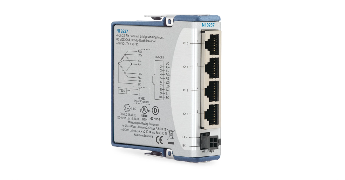
For bridge type sensors and most strain gauges configurations (full and half bridges), our engineers will opt for the NI-9237 C-Series module to acquire strain and bridge data instead of the NI-9235 or NI-9236 modules. Unlike the NI-9236 module, the NI-9237 can acquire data from:
- Any resistance strain gauge (not just 120 or 350 Ohm)
- Quarter, half, and full-bridge strain gauge configurations
- Torque and load cells (off-the-shelf and custom)
The NI-9237 is a 4-Channel C Series strain/bridge input module that contains circuitry to power, scale and calibrate strain and load sensors . For quarter and some half bridge measurements a bridge completion module must be used in conjunction with this module. The NI-9237 module provides internal bridge excitation (2.5V, 3.3V, 5V, or 10V) and shunt calibration resistors for sensor scaling verification. To collect synchronized and scaled high-speed (50kHz) structure strain and load cell data, use our iTestSystem engineering measurement software.
For more information about the NI-9237, DAQ module rental, strain gauge installations or our data logging solution iTestSystem, contact Ryan Welker via email: ryan.welker@itestsystem.com or phone: (844) 837-8797 x706.
iTestSystem Tip: Sensor Auto-zero Utility Update
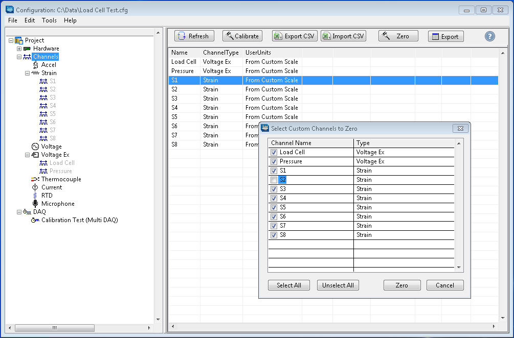
Our iTestSystem customers who routinely acquire data with high channel counts and data from full-bridge transducers recently requested that we update the sensor auto-zero utility to improve test setup efficiency. In the latest version of iTestSystem, we updated the sensor auto-zero utility to include all channels that use the From Custom Scale option. This update enables users to quickly adjust selected channel offsets with only a few mouse clicks.
One of our test engineers recently used this feature to test and calibrate a new load cell design for measuring loads in a manufacturing process. He was able to quickly calibrate and zero the strain gauges along with a calibrated load cell and a pressure transducer prior to testing and before each directional test. The offset values are included in the calibration data files for traceability.
Contact Information: For more information about this update or iTestSystem contact:
Chase Petzinger – Integrated Test & Measurement (ITM), LLC. Email: chase.petzinger@itestsystem.com or Phone: 1.844.TestSys
Strain Gauge Installations for Field Testing
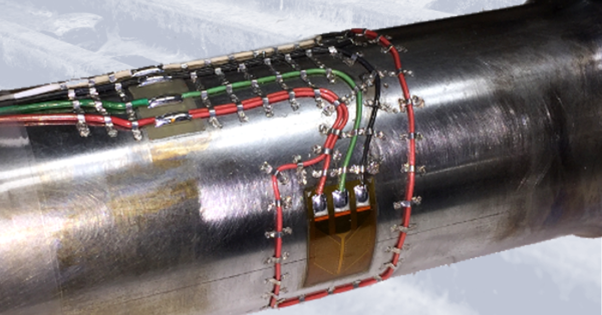
Image1: Shaft torque strain gauge installation example for field testing
Our engineers and technicians have epoxied, soldered and spot welded strain gauges for applications ranging from high temperature exhaust systems to miniature load cell measurements. Every application requires a unique understanding of the strain measurement requirements including installation environment.
If the strain gauge installation is to survive in the field you must plan for the conditions it will undergo. Three important variables that you should account for are temperature range, liquid exposure, and potential impact forces. These variables determine the type of strain gauge, epoxy, solder, wiring, coating, and impact/wear protection to use in the application. The table below shows which variables affect your installation choices.
| Gauge | Epoxy | Solder | Wiring | Coating | Covering | |
| Temperature | ||||||
| Liquid Exposure | ||||||
| Impact Forces |
Table1: Strain gauge installation variables
For more information about ITM’s strain gauging services contact Ryan Welker at email: ryan.welker@itestsystem.com or phone: 1.844.837.8797 x702
ITM provides software development, structural and mechanical testing services, industrial monitoring, strain gauging, and data analysis solutions to clients on six continents. ITM is a recognized National Instruments Gold Alliance Partner.
![]()