
Modern Tools Series: What’s In The Box?
Modern Tools Series: What’s In The Box?
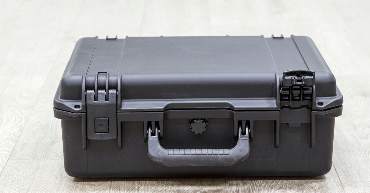
This box reveal may not be quite as dramatic as the ending of “Seven,” the ’95 serial killer thriller that blew moviegoers’ minds, but the ITM team is throwing open the latches nonetheless.
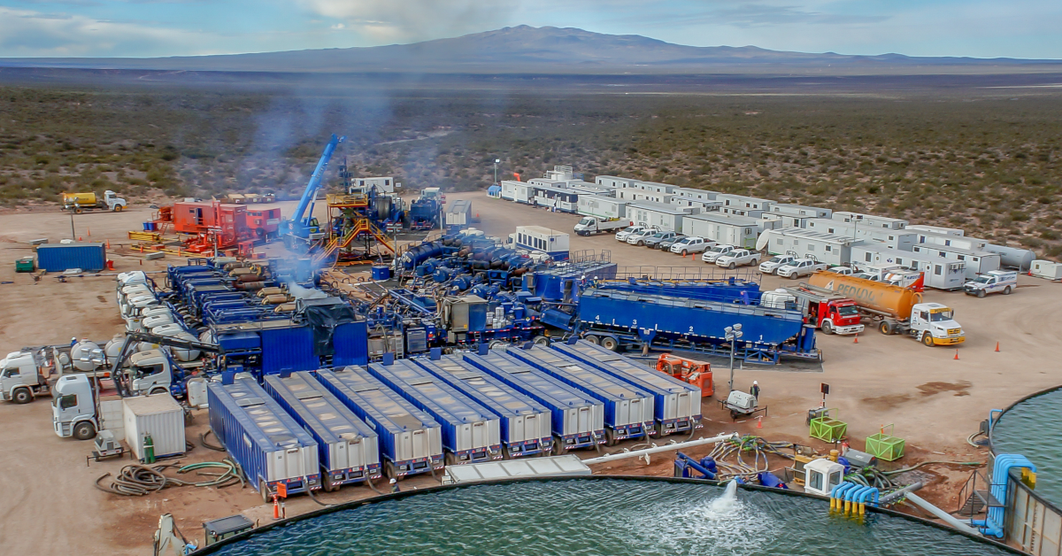
In this case, our team is taking you on a quick tour of a recently deployed Rugged Data Acquisition System. These particular black boxes of tech are riding around on high-dollar fracking equipment to remotely monitor all sorts of triggering events. Our crew builds them on the regular, and the end result is that our clients can better understand what sorts of stress, strain and vibration is taking place both en-route to their site and once operations begin.
ITM is known for building rugged measurement systems and data logging solutions that are deployed on everything from Class A trucks, to well frac trailers, to dam and bridge structures, oil pipelines, gensets, boilers and more.
So, without further ado, what’s in the box?
We recommend a handful of essential components and elements if you are looking to build your own rugged measurement system:
- An Industrial Embedded PC. We love the Nuvo-7000LP. Another favorite is the Advantech UNO-2484G-9S55.
- You’ll need industrial grade connectivity, and you can’t beat Peplink’s cellular router options. And remember to outfit that unit with an AT&T or Verizon plan and get that activated card installed.
- A remote desktop application is a must, and we usually turn to LogMeIn for our remote access and file management. This allows us to pull up any of our units no matter where they are in the world to check in on status or grab some data for our clients.
- Speaking of data, depending on your job, you’ll likely need lots of data storage capability. Our preference is a 2 terabyte USB drive, which gives us an almost unlimited amount of space. If needed, we can store about six months worth of data before hitting capacity.
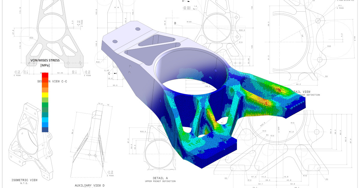
- Since our industrial PC is running Windows, we use iTestSystem, our proprietary engineering measurement software platform that enables test engineers to organize, acquire, view, and analyze data from machinery, processes, vehicles and other complex systems.
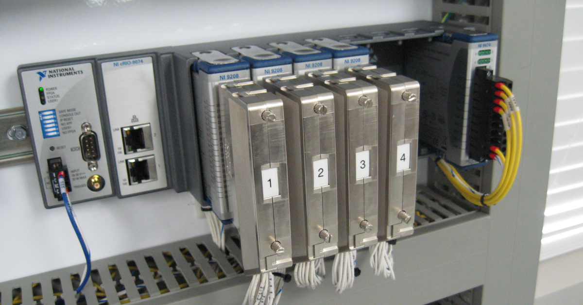
- To complete the box, our industrial PC is connected to an NI c-DAQ outfitted with strain, vibration and voltage modules.
- What about power you ask? In our fracking instance, we connected to an alternator which charges a bank of batteries in the RAC.
So there you have it. That’s what’s in the box. Build your own, or get in touch with our team, and we’ll customize a system for your specific needs.
We also install and service all of our equipment. So if something breaks in the field, we can get you back up and collecting data or even assist with data analysis.
For more information about our rugged data acquisition systems, on-site system deployment or data analysis services, contact Josh Fishback via email at josh.fishback@itestsystem.com or phone at (844) 837-8797 x705.


