ITM Engineers Strain Gauge in Shadow of Artemis I Rocket Launch
Engineers Test Artemis I Spacecraft Orion at Johnson Space Center
ITM strain gauge team witnesses powerful forces during two-week trip to Cape Canaveral
A group of engineers and aerospace engineering technicians from Integrated Test & Measurement just returned after an unforgettable experience in Cape Canaveral.
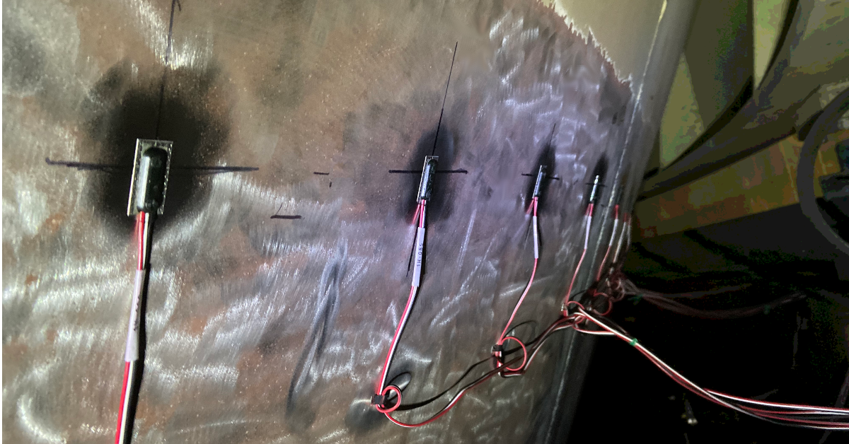
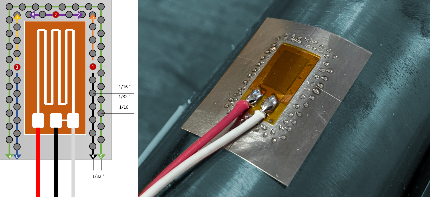
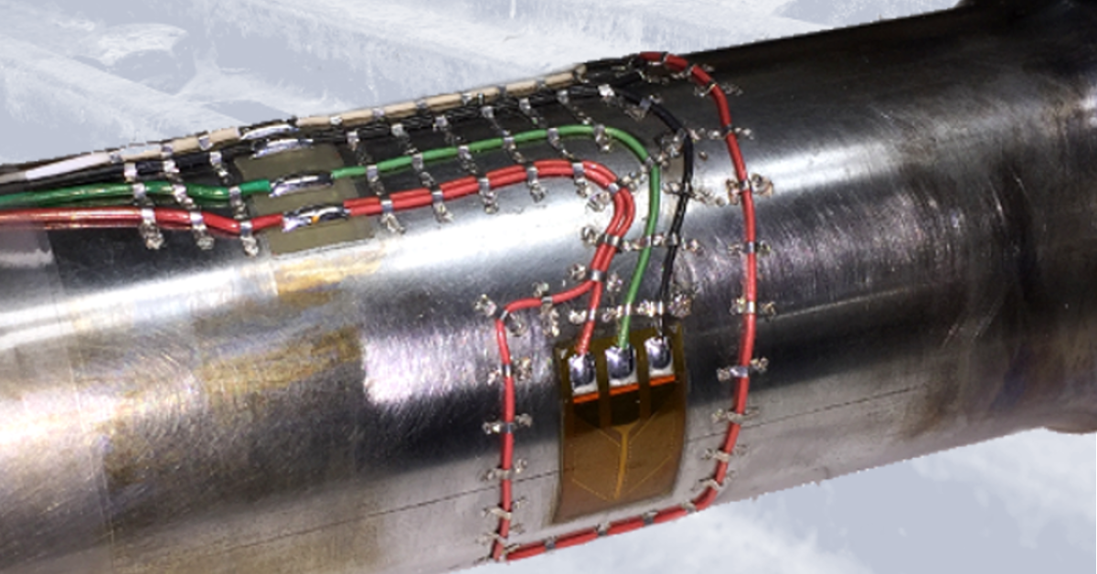
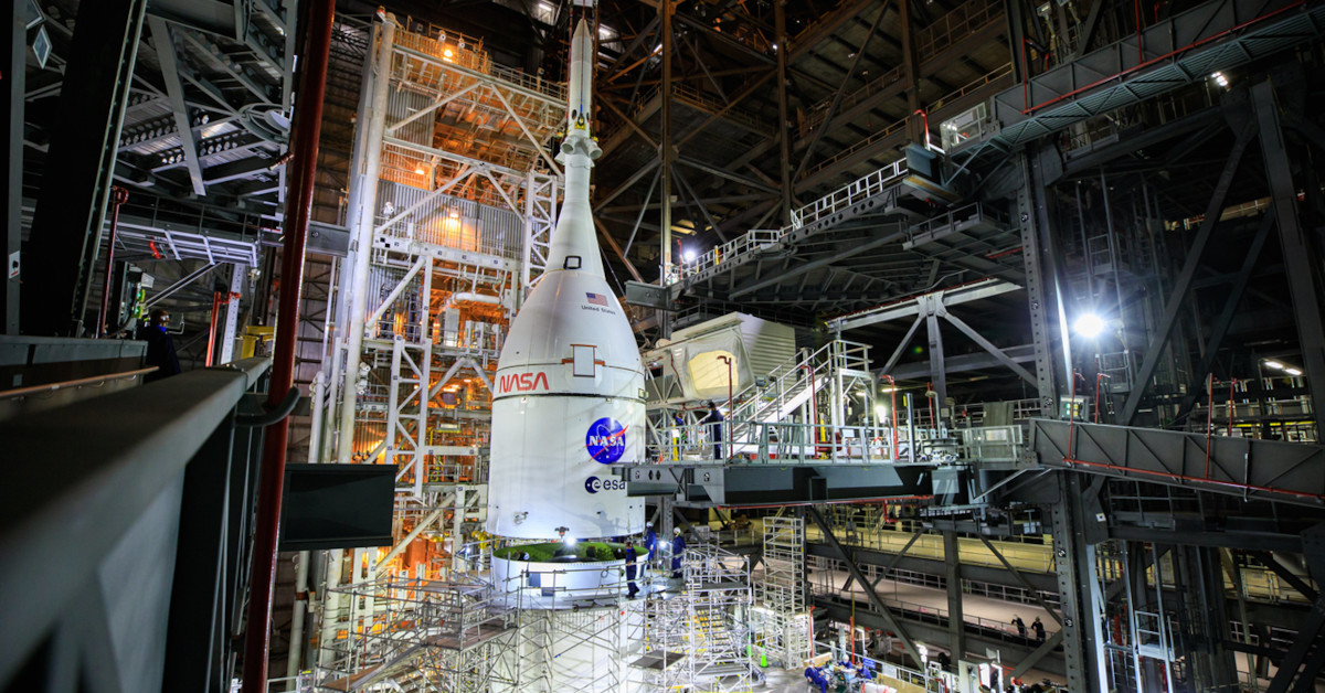
ITM’s team was there to assist an aerospace engineering partner with on-site strain gauging. The challenge was to assist in validating rocket components ahead of an upcoming launch, which required completing a massive strain gauge instrumentation project.
ITM’s team was there to assist an aerospace engineering partner with on-site strain gauging. The challenge was to assist in validating rocket components ahead of an upcoming launch, which required completing a massive strain gauge instrumentation project.
The team’s work was delayed due to Hurricane Nicole, so they waited out the storm just blocks from the beach, said Ryan “RJ” Matthews, ITM engineer. As powerful as it was seeing a storm with wind speeds exceeding 130 mph, the hurricane was still a distant second in the most memorable department to their up-close view of NASA’s Artemis I mission rocket launch.
Matthews said the team took a break from strain gauging a rocket booster, an intense project that required a significant amount of cable routing, to observe the launch from just a few miles away.
To accommodate their partner, ITM’s crew worked eight 12-hour shifts from 5 p.m. to 5 a.m., so perfect timing to watch NASA take a first step toward blazing a path back to the Moon in the early hours of Nov. 16.
About 45 minutes after the anticipated launch time, fireball from the SLS Rocket lit up the night sky.

Artemis I SLS Rocket Launch Time Lapse
“It was incredible,” said Matthews, who witnessed the launch from a balcony. “It was super bright — kind of like a 1-minute sunrise. About 40 seconds later, it started rattling the building.”
Contact us for more information about our aerospace, strain gauging and testing services.