Printed Circuit Board Strain Testing – JEDEC-9704A

ITM Employs JEDEC-9704A to Test Strain on Printed Circuit Boards
ITM Employs JEDEC-9704A to Test Strain on Printed Circuit Boards
Every modern electronic device includes at least one printed circuit board, so it stands to reason that these intricate parts fail at times due to stress and strain.
When that happens, manufacturers know they can turn to ITM’s test engineers who can develop tests to help get to the bottom of their circuit board problems. For some, the failures are happening in the field, and for others, it’s the manufacturing process that’s overstressing the parts that make all our gadgets go.
Engineer Ryan “RJ” Matthews said ITM has decades of experience with printed circuit boards (PCBs), including circuit board design and development. So, strain gauge testing on PCBs using JEDEC-9704A, the global standard for microelectronics, is a natural progression for the team.
Matthews has led recent projects in which ITM helped companies determine how much strain and stress their PCB is experiencing both in the field and during the assembly process. Simulating the assembly process can be a daunting challenge, particularly if that process includes variables such as high heat, as it did in a recent example.
Still, the team was able to instrument the circuit board effectively and replicate every assembly step while also gathering crucial strain data, which they reported back to the client. The challenging test environment isn’t unlike ITM’s typical rugged data acquisition projects, just on a much smaller scale. The firm specializes in strain gauge data collection on everything from behemoth off-road machinery to miniscule gadgetry.
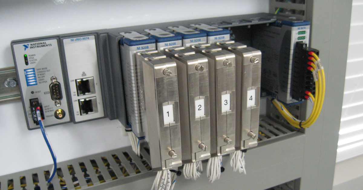
Matthews said the team often employs NI c-DAQ hardware combined with ITM’s proprietary iTestSystem software, which allows them to easily configure PCB tests to collect and analyze the data. iTestSystem’s Rosette Analysis tool is used to calculate the principal strain, principal strain angle, shear strain, principal stress, and other values from strain gauge rosette data.
For more information on this work, our strain gauge testing services or iTestSystem, contact: Ryan Welker – Integrated Test & Measurement (ITM), LLC – ryan.welker@itestsystem.com