Automate Complex Analysis of Engineering Data Using iTestSystem
Does your project involve the need to deploy unattended or “black box” data acquisition systems in the field? If so, our engineering software known as iTestSystem, a proprietary product developed by Integrated Test & Measurement, may be the ideal solution.
In this blog, a new series by ITM, we’ll share details about iTestSystem’s “Automated Analytics” feature, which is commonly used to to constantly analyze strain and vibration data on machinery, vehicles and industrial processes.
By using the Automated Analytics feature in iTestSystem, engineers are able to greatly simplify processes that require hunting down system operation outliers or damaging events. The Automated Analytics application allows users to analyze, build, and send sensor level reports only when specific vibration and strain limits are exceeded. In the end, that leads to a massive time savings. Instead of searching through streams of data files, engineers can easily review the report and download relevant data files from deployed systems for further analysis.
Here’s how Automated Analytics works:
Rather than getting buried in a mountain of raw data files that require processing later, users can easily set up an automated routine using iTestSystem’s Automated Analytics — just one feature among the many analysis applications built into the latest version of this powerful tool.
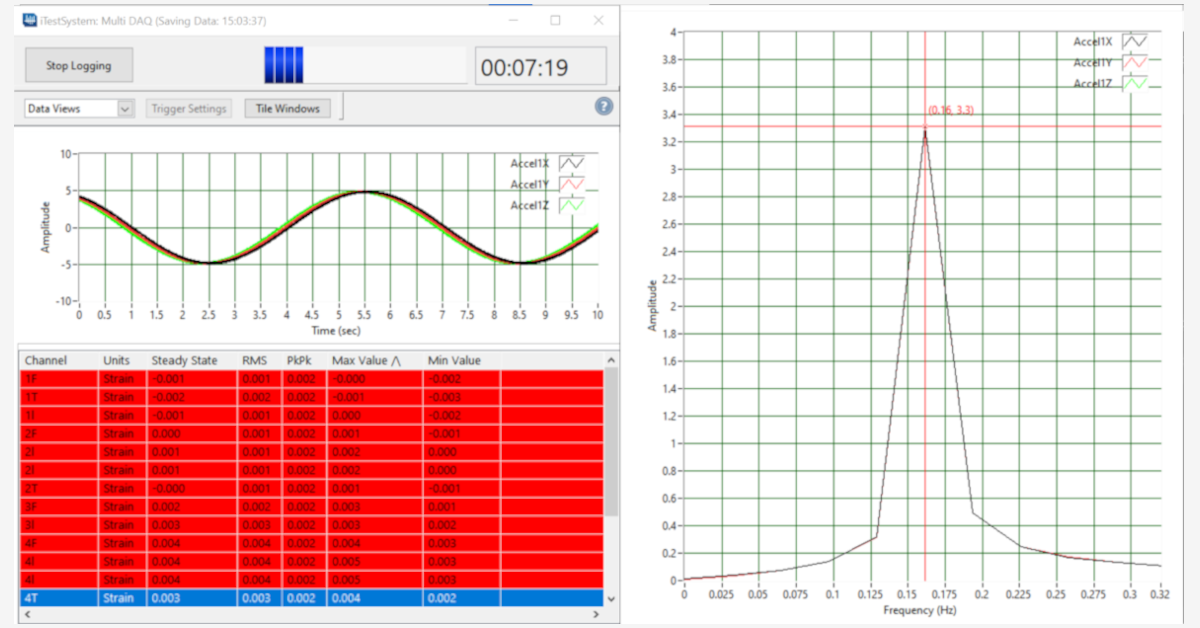
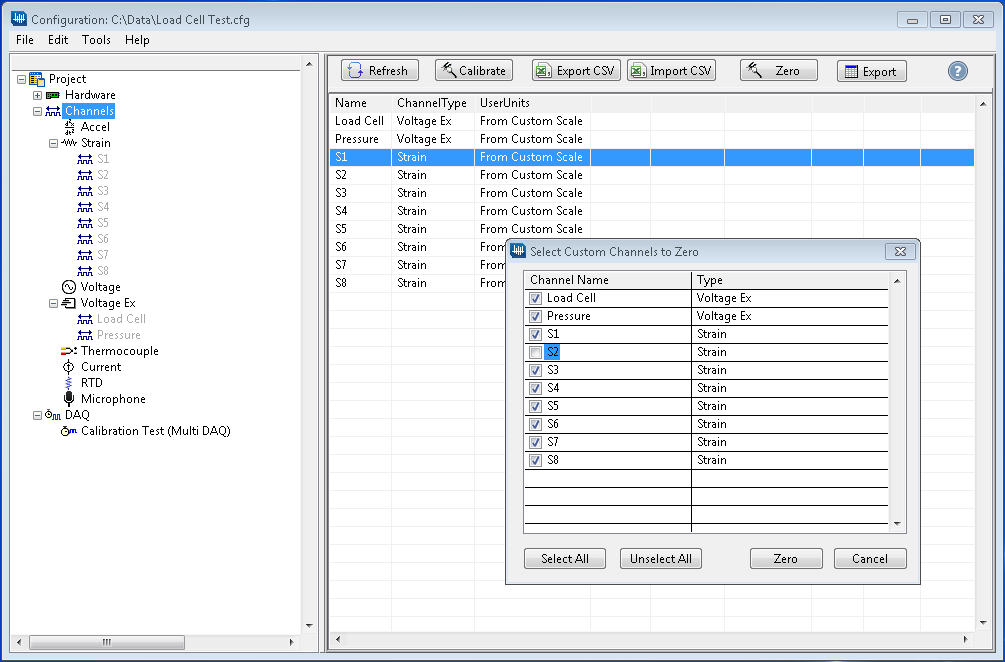
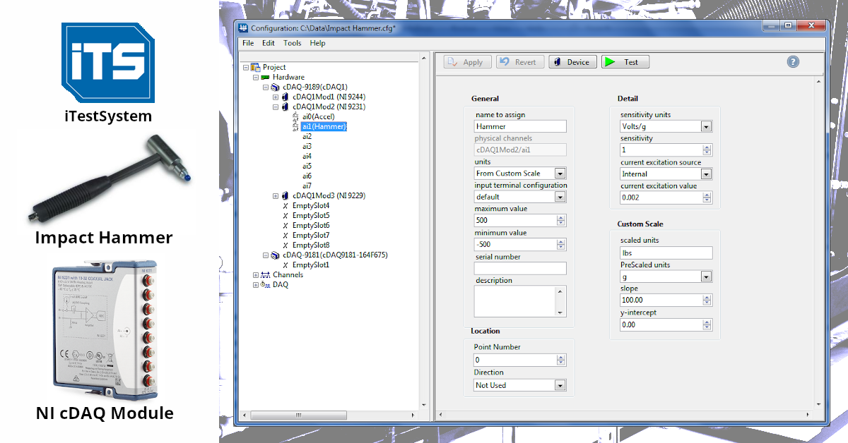
Once you’ve configured your cDAQ hardware, project path and sensor channels in iTestSystem, set up your MultiDAQ and record a sample TDMS file. Then simply open Automated Analytics to set up and run a new automation.
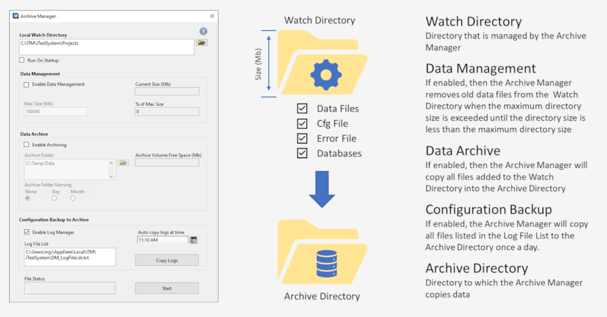
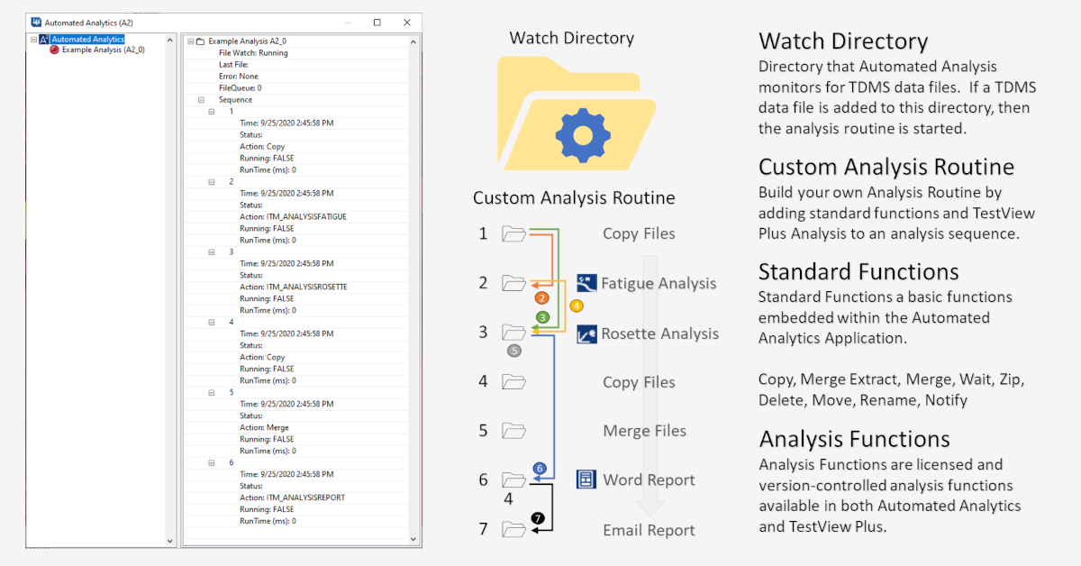
Users assign a “Watch Directory,” and any TDMS files they pull into that directory will have the automated sequence of events they chose applied to those files automatically. Simply click into the properties for any file to reveal the newly embedded statistics or analysis data within.
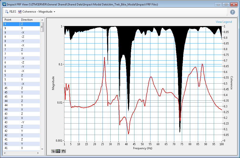
Users can pair the Automated Analytics feature with the power of Notification Services, an iTestSystem feature that allows reports — including helpful graphs — to be automatically sent to them daily, weekly or whenever most useful. This feature is especially beneficial if engineers do not have access to the equipment being monitored.
Stay tuned for additional iTestSystem features, including the ability to set up Trigger Analysis events so reports are only dispatched when the data reaches a certain threshold.
About iTestSystem
iTestSystem is an engineering measurement software platform that enables test engineers to organize, acquire, view, and analyze data from machinery, processes, vehicles and other complex systems. iTestSystem was specifically designed for use with National Instruments (NI) cDAQ hardware for data collection and data logging.
For more information about our iTestSystem or ITM’s testing services, contact Ryan Welker @ (844) 837-8797 x702.